Aachen, Germany - The Fraunhofer Institute for Laser Technology (ILT) says it has developed an offline programming system that helps generate tool paths for laser material deposition.
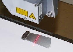
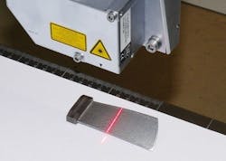
Laser material deposition (LMD) offers minimalized heat input and low levels of distortion vs. conventional processes, plus high degree of process accuracy and combination with automation. In using LMD as an additive manufacturing process, a CAD model of a part is split into horizontal, cross-sectional layers corresponding to the direction of the part's build-up, which are filled out using equidistant tool paths or parallel paths projected onto the welding surface. The part's geometry is measured using a laser line scanner to generate a point cloud, from which a surface model is reverse-engineered. The volume of defect is determined by calculating the best fit between the actual geometry and the CAD model of the component, and is then built up using LMD.
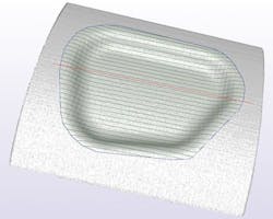
The Fraunhofer ILT's LaCam3D program, an in-house prototype for the past two years and debuting at Euromold later this month (Nov. 27-30 in Frankfurt), provides functionality that allows for modification of the LMD sequence and welding direction of individual paths, through parameters such as laser power and velocity. Users can choose between equidistant tool paths and parallel paths projected onto the surface of the layer, which are automatically cropped to keep within the boundary marking the edge of the defect area. Paths are planned to allow enough oversize for the subsequent finishing process that machines excess material. A simulation tool can check in advance whether the planned LMD process will cause the laser processing head to collide with the part. An integrated postprocessor generates the machine code supporting a range of different systems.
The program's modular structure allows integration of additional algorithms of particular LMD strategies -- e.g. there's a specially designed module helps plan paths for turbine parts made with additive manufacturing, with other (unspecified) modules able to extend the program to other applications.
The equidistant set of lines is trimmed by the edge of the welding area in blue. (Source: Fraunhofer ILT)


