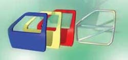
Expanding usability by enhancing joining part sizes
The use of polymeric materials is continuously increasing in almost all industrial sectors,1 especially in the automobile industry, where this has been a trend for several years. In autos, polymers replace metals and glasses.2-4 The employment of polymeric materials offers numerous advantages such as: cost savings (material, manufacturing, energy consumption), weight reduction, corrosion resistance, electrical isolation, freedom of design, aspects of security and convenience, environmental protection, and sustainability due to recycling.2-5
Weight reduction becomes possible when either several small or a few large polymeric parts replace components of higher density. On one hand are single segments, on the other hand are large components joined to generate large end-products.
Frequently, the spectrum of industrial laser welded polymeric products ranges from micro to macro. This spectrum is limited on both sides.6 At present, product dimensions of laser welds typically range from the size of a marble (such as a hearing device7,8) to the size of a soccer ball (car lights9). Common weld seam widths are between 100µm and a few mm. Producing small widths requires an excellent thermal contact between the joining parts.6,10 Also, welding of large-scale polymeric components poses technical challenges.
Definition and hurdles
Enhancing the joining part sizes poses two questions: How is a large-scale polymer component for laser welding of polymers defined? Which technical hurdles appear with increasing joining part size? In the following, both aspects will be illuminated as well as answers presented.
A polymeric laser welding joint is defined as large-scale if the following aspects are fulfilled:
- ) Both joining parts have extensions larger than a soccer ball.
- ) The joint geometry is spatially expanded and not necessarily within one plane
- ) The joint geometry is not segmented into multiple weld seam sections but is closed in itself or the joint geometry may not be irradiated completely by only one scanning system.
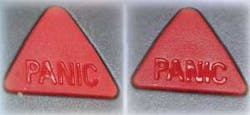
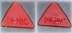
Left: no interaction marks because of appropriate polymer modification [Treffert];
Right: interaction marks because of too large optical penetration depth.
The interactive relations between joining part properties and process technical necessities leads to technological hurdles.
Besides polymeric compatibility laser welding has two demands: both joining parts have to show different optical properties and, preferably there is no gap between the parts.6
However, with increasing part sizes, the technological hurdles grow. The direct injection molding process loses reproducibility of dimensional stability with increasing part size. Larger part dimensions may negatively influence shrinkage and tolerance performance and with this the quality of local optical properties and thermal contact between the joining parts. Additionally, several products do not accept interaction marks on visual surfaces. Figure 1 shows, on the left side, the backside laser welded part (thickness: 1mm), which has no interaction marks. However, the picture on the right shows interaction marks, which hamper the readability of the word PANIC.
Those marks are caused by morphology changes due to temperature distributions from the joining area up to the visible surface. But the reason for interaction marks lies not only in the applied process parameters; rather, the interactive relations between thickness of the absorbing joining part and the absorber concentration correspond to a certain interaction depth. An insufficient thermal contact heightens the risk of interaction marks. To bridge a gap between the joining parts, a longer interaction time and more energy input is necessary. This corresponds to an expanded temperature distribution, which makes interaction marks more likely (see Figure 2).6 The absorber concentration has to be tuned in a manner that an industrial acceptable process window, sufficient gap bridging, and avoidance of interaction marks is guaranteed.
Additional hurdles are the increased clamping requirements. The larger and more complex the joining parts the more extensive the clamping technique to ensure a homogenous clamping pressure over all the weld seam area and a thermal contact without generating inherent tensions in the weld.
The aforementioned technological hurdles—to guarantee gap bridging capability and freedom of interaction marks at the same time, by means of joining part design, absorber concentration, and clamping—are additionally heightened due to the demand for products of less weight. Lower weight often corresponds to thinner thicknesses of the joining parts.
Example: window
One example of a large-scale laser welded unit is a two-plate polymeric window (see Figure 3). Formerly, both polymeric plates were glued into the frame; the disadvantages were the time, storage area for glue hardening, running costs, work place contamination (vapors), and the extensive handling. Replacing this process by laser welding lowered material and personnel costs, eliminated hardening times and storage areas, and avoided any contamination.
By means of a laser adapted part design and clamping technique two instead of five employees were able to manufacture the same number of pieces per hour. Employing a 100W diode laser system, feed rates of 8 m/min were realized. In a second step the rectangular frame corners were replaced by a rounded design. Thus, the acceleration in the corners and the demands on the handling system have been lowered. Feed rates up to 12m/min were possible. However, the clamping system and effort may be seen as adversarial. An easier, robot-guided clamping system, such as Globo-welding, could facilitate handling as well as improving flexibility of product or design changes.
null
The Globo-welding system
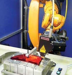
The classical concepts of laser welding are, due to the interplay of clamping device and beam guiding, usually limited to 2D application. The Globo Concept, however, allows 3D and large-scale applications by performing without complex clamping devices. The prime difference to the conventional concepts is the design of a dynamic clamping device, where the clamping pressure is variable and always applied perpendicular and orthogonal to the welding zone (see Figure 4). This is accomplished by an air-supported glass sphere that is rolled along the joining area.
A Globo-welding system consists of a radiation source, optics, and the handling system. As a radiation source, a fiber-coupled diode laser is used. The optic includes the beam forming and guiding, a dynamic clamping device, and optional process control. The beam guiding optical system allows the adjustment of the focal position and thus the width of the weld seam. The glass sphere, serving as a dynamic clamping device, is air-supported and functions as an optical instrument in the beam guiding system. Process control is via sensors and camera systems.
Usually, handling of the Globo-optic is performed by the robot system’s program that ensures the clamping pressure applied by the optic is always orthogonal to the welding zone. This allows for a component specific application of the clamping pressure along 3D-weld seam geometry. Furthermore, a signal supplied by the robot, which is proportional to the traverse speed, can be used to adapt the laser power to the traverse speed.
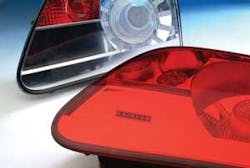
One application of the Globo-welding system is 3D rigid components such as tail lights with sculptured surfaces (see Figures 5 and 6).11,12 For large components, Globo-welding allows for secured clamping due to its perpendicular application of clamping pressure. This allows shorter interaction times corresponding to lower energy inputs. This results in shorter processing times and avoids interaction marks.
Conclusion
The joining of larger polymer parts will extend the industrial employment of laser welding of polymers. Motivating aspects are product specific benefits as well as options concerning innovative processing concepts. For example, diode lasers find increasing usage in large-area joining of coiled carbon fiber reinforced components. Other application potentials are in the field of orientated polymers as well as large polycarbonate parts (roof components). The use of laser radiation for larger parts allows decreased costs and cycle times as well as insertion of process monitoring and control, while guaranteeing process stability and product quality.
A tailored polymer part (see Figure 7) is the term for joining different polymers. The goal is to meet locally required product properties (mechanical, optical, acoustical) by means of joining components of different polymeric materials. Basic experience has been acquired in R&D projects. Polymer compatibility, optical properties, and thermal contact between the joining parts are being determined.
Aside from joining polymer parts, the laser also offers disassembling at the end of the product life time cycle. This allows materials separation and sustainability due to recycling and resource protection.
Material properties, beam guiding and forming, and clamping techniques as well as production plant concepts have to be adapted to the laser processing. Continuous consideration of laser radiation as a joining tool for larger polymer parts facilitates innovative implementations in which process stability and product quality can be guaranteed and cost and cycle time reduced. The future will show whether a large R&D effort will lead to laser beam welded “large-scale” polymer parts.
References
- W. Wunderlich, Erfolge im globalen Wettbewerb — Deutsche Kunststoffindustrie behauptet ihre führende Stellung, Kunststofftrends, Jan. 2008, p. 6-7.
- Polymere sorgen für automobile Leichtigkeit, VDI Nachrichten, 41—2007, p. 19.
- Ein ungeliebter Werkstoff macht Karriere — Hightech aus Plastik, VDI Nachrichten, 42-2007, p. 38.
- M. Wissmann, Automobile Zukunft —Der Beitrag von Kunststoffen zum Klimaschutz, Kunststofftrends, Jan. 2008, p. 12-13.
- Interview Porsche AG: Auf der Überholspur — Einsatz polymerer Werkstoffe im modernen Automobilbau, Kunststofftrends, Jan. 2008, p. 14ff.
- U.A. Russek, Prozesstechnische Aspekte des LaserdurchstrahlschweiBens von Thermoplasten, Dissertation RWTH Aachen, 2006.
- Jie-Wei Chen, A. Daenzer, C. Leister; LaserschweiBen im Maskenverfahren, Laser, p. 22-26, Heft 3, 2002.
- Oliver Hinz, Jürg Nö tzli, Cerumenschutz: Besser hö ren durch LaserschweiBen, Laser, p. 8—11, Heft 1, 2008.
- Oliver Hinz, Fügedruck inbegriffen - Globo-Welding, Joining Plastics 1/2007, p. 22-23.
- . DVS Richtlinie 2243, LaserstrahlschweiBen thermoplastischer Kunststoffe, DVS Beiblä tter zur Richtlinie 2243.
- Jie-Wei Chen, Die dritte Dimension, Kunststoffe, Nr. 5, 2004, p. 86-88.
- C. Thielen, J.-W. Chen, Globo-Welding - Ein innovatives Konzept für das 3D-Laserfügen von Thermoplasten im Durchstrahlverfahren, Laser Technik Journal, Nr.2, October 2004, p. 35-38.
U.A. Russek ([email protected]) and T. Fox are with Huf Tools GmbH, Velbert, Germany (www.huf-tools.de). C. Thielen and C. Wenzlau are with Leister Process Technologies, Aachen, Germany.
