Transparent and nontransparent plastics are weldable with high precision and efficiency
XIAONONG ZHU and SHIBIN JIANG
Over the last decade, significant progresses have been made in the development of various thulium-doped fiber lasers with a central wavelength near 2μm [1]. These newer 2μm fiber laser products range from 200W average power for continuous-wave (CW) operation [2] to 10kW peak power in pulsed mode operation [3, 4]. It is also possible for manufacturers to tailor the 2μm laser output performance according to specific application needs.
Much of the existing 1μm fiber laser technologies can be borrowed in constructing industrial-grade 2μm lasers. Many silica- and silica-fiber-based components commonly used in the visible and/or 1μm spectral regions may be also deployed in 2μm laser systems, except that their coatings are specified at different wavelengths.
Thus, the general performance of 2μm fiber lasers can be nearly as robust as their 1μm counterparts, especially in regard to compactness, efficiency, stability, and ease in daily operation, should their production be ramped up to meet any larger-scale potential applications.
Advantages of 2μm laser processing
Considering the vast amount of existing industrial applications for other wavelengths, why, when, and where would one need to consider 2μm lasers? The answer lies mostly in the absorption spectra of the materials to be processed [5]. For certain materials such as polymers where 1 or 0.8μm light is absorbed too little and 10μm or ultraviolet (UV) light is absorbed too much, 2μm may provide a new avenue of suitable light absorption. Some existing applications of UV to 1μm lasers can be also fulfilled with 2μm lasers, being much more eye-safe (retina-safe). Another wavelength-dependent aspect in laser material processing is beam focusability. At 2μm, these lasers represent a compromise between 1 and 10μm lasers in terms of minimum focusing spot diameter or pitch size for a given processing task.
Applications for 2μm lasers include transparent plastic welding [6, 7], embedded or multiple-layer marking of plastic panels, and precision thin polymer film welding and cutting. Note that for embedded marking, little or negligible damages on the front surface are possible. These unique applications may not easily be implemented with other wavelength lasers.
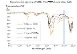
"Transparent" means it is clear in the visible spectral range, but not necessarily transparent at other wavelengths. It happens that many plastic materials, intrinsically transparent in the visible, also have high transmission around 1μm, but not so at the wavelength near 2μm. This is evident in the measured transmission spectra given in FIGURE 1 of four different types of transparent plastics: polymethylmethacrylate (PMMA), polycarbonate (PC), cyclic olefin copolymer (COC), and acrylonitrile butadiene styrene (ABS). From the spectral traces in FIGURE 1, it may be estimated that the respective absorption coefficient is at 2μm of 1.27/cm, 0.81/cm, 2.26/cm, and 1.38/cm for the four common plastic samples, whereas their corresponding absorption at 1μm is significantly less or negligible. Separate measurements of the transmission at the wavelength of 10μm for these samples, however, shows a transmission of less than 0.3%, corresponding to an estimated absorption coefficient of at least 58/cm or larger.
The spectral traces shown in FIGURE 1 also tell us that the absorption near 2μm is relatively flat, as the 2μm wavelength actually sits between two major absorption peaks—one around 1700 nm and another around 2150 nm. Based on the absorption coefficients derived from the transmission measurements for the four different transparent plastics, it may be deduced that at 2μm wavelength, with COC having highest absorption, it would be easier to weld compared with ABS, PMMA, and PC, whereas the PC sample with the lowest absorption per unit length would require significantly more power to weld. All of these are consistent with what we find in experiments.
Light absorption in plastic materials can be characterized into three basic categories: very strong absorption, very little absorption, and moderate absorption in between. The first category can cause effective surface heating, such as the majority cases where CO2 lasers at 10μm or UV lasers are used. In contrast, the second category would often lead to no machining unless the laser power density is extremely high, such that the defects and/or the laser-enhanced defects become strongly absorptive and thus result in a sharp localized temperature rise followed by catastrophic ablation. The third category is where the 2μm laser light propagating inside polymers falls into. Here, light penetrates through the sample to a relatively longer distance, but in the meantime is attenuated because of absorption, thus heating up the sample.
In terms of effect on material processing, this third category of absorption produces volume heating in general, and because of this it also provides the opportunity of marking at different layers for transparent or translucent plastics. In such cases, the front surface damage (or undesired deformation) at the beam entrance may be effectively reduced or even avoided through selecting appropriate numerical aperture of the focused laser beam and properly placing the workpieces in respect with the laser focus, plus the auxiliary means of surface cooling.
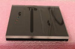
It should be added that not only the transparency, but sometimes also the darkness (or blackness) that appears in the visible spectral range, could be different at 2μm or another invisible wavelength. As demonstrated in FIGURE 2, laser welding of two pieces of PMMA plates—one clear (5.32mm thick) and one black (5.62mm thick)—can be achieved with the 2μm laser beam going through the black PMMA, rather than the other way around as we would usually expect. Actually, in this case, launching the laser from the clear piece fails to produce a solid bonding, which corresponds to the three shallow welding marks (one on the left and two on the right of the black welding track).
What is the explanation for this? The black is simply not black at 2μm! Using the same laser parameters and letting the 2μm beam enter from the clear PMMA, the corresponding maximum thickness of the clear PMMA piece that may lead to a good weld or strong bonding is about 4.8mm. This is apparently inferior to that obtained by welding through the black piece.
Parameter windows for 2μm laser processing
For a given processing job, finding the best processing parameter windows with a 2μm laser is essentially the same as with other wavelength lasers. It normally includes trial and error in the selections of laser power or pulse energy, the laser beam diameter at the surface of workpiece, the scanning speed, and the relative movement pattern of the laser beam. With both pulse duration and pulse repetition rate often preset by laser manufacturers, the above-mentioned common variables represent the most important adjustable parameters for a laser processing engineer. This is no exception in using 2μm lasers.
For laser power selection, an optimized value should be sought between a minimum (threshold) and a maximum (overexposure). In some processing cases, a combination of either high power with greater beam moving speed or less power with lower speed (and longer processing time) would work. However, it may be more desirable to choose the high-power option so that the overall speed of processing can be increased as much as permissible, providing that the processing quality remains satisfactory.
Besides the laser power/pulse energy and the beam size at the processing site, the beam scanning speed directly affects the amount of effective laser dose at any given position for a given period of time. This is where the pulse repetition rate plays an important role. Once a beam scanning speed is chosen, higher repetition rate means greater spatial overlap between the laser-material interaction spots associated with any neighboring pulses, resulting in a higher effective number of pulses that strike at a given location.
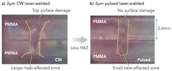
Sometimes the basic question in welding is whether a pulsed or a CW laser should be used. FIGURE 3 shows a comparison between the cross-sections of PMMA welding with respective CW and pulsed 2μm lasers under a similar processing condition. It can be seen that for the pulsed laser welding result on the right, there is no observable front (top) surface damage and no gap present at the welding joint. But for the CW laser welding, noticeable top surface deformation and incomplete weld are present, along with a noticeably larger heat-affected zone (HAZ). Thus, it may be concluded that for precision transparent plastic welding, a pulsed 2μm laser with suitable specifications may be preferred, as it can lead to smaller welding feature with lower average power and better quality of weld.
Examples of processing plastics
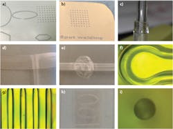
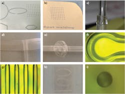
FIGURE 4 shows some thin transparent or translucent plastic samples processed with a commercially available 20 kHz, 180 ns, 2μm laser, which has a maximum average power of 10W. The dot separation of ~1.5 mm for spot welds in FIGURES 4a and 4b gives us an idea of the scales of these micro-welds. Normally, these welded parts cannot be peeled off easily unless damaging the samples. As shown by the laser-written "spot welding" in FIGURE 4b, the highly localized melt (and solidification thereafter) also provides an effective approach to marking these thin plastic materials. In other words, it is possible that both welding and marking may be achieved using the same 2μm pulsed laser for some transparent polymers.
Welding with a 2μm laser is by no means limited to only transparent or translucent thermoplastics. Colored or white plastic and some thermo-elastic materials may be also bonded with sufficient strength by using 2μm laser light. The latter would have great potential in biomedical applications. Precision 2μm laser welding of thin polysulfone strings, polyvinyl chloride (PVC) tubes, IV bags, and polyurethane balloons have produced promising results, and FIGURES 4c through 4e show examples of laser-welded PVC tubes, a section of an IV bag, and an internal retention balloon. Besides the cosmetic aspects, all of these welding jobs require good seal for liquid under certain pressure.
Bonding of microchannel devices or biochips is another area incorporating 2μm lasers, and the interest in this application is increasing. Compared with the conventional hot plate bonding method, use of a 2μm laser to weld and seal microchannel devices—including all channel paths and their entry/exit ports—offers advantages in precision, energy efficiency, and flexibility, which should also help to significantly reduce the prototyping time. FIGURES 4f and 4g show the representative micro-welding tracks on a PMMA sample using a pulsed 2μm laser. The width of these thin welding lines can be readily controlled according to the design of micro-channel devices. While the width of these welding lines can typically be between 0.3 and 0.5mm, even thinner welding tracks are possible.
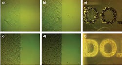
FIGURE 5 shows the results of surface marking of a PC sample using a pulsed 2μm laser. As shown on the left, with different amounts of laser exposure, the darkness of the laser-processed area can be gradually altered in a well-controlled manner. In particular, both black and clear marks (FIGURE 5, at right) may be achieved. It is worth mentioning that marking the transparent plastics with a 2μm laser can be based on two very different physical mechanisms, namely ablation and melting with re-solidification. For the latter, it is possible that rise in temperature in the later process may cause these marks to disappear if the temperature reaches beyond the melting point of the chosen plastic material. In contrast, the ablation-generated marking would normally survive the aftermath of a period of enhanced heating. Nevertheless, the ablation-based marking, often accompanied with unwanted cracks and chips, is likely linked to some more severe structure damage to the material and this would also not be preferred. Therefore, a delicate marking scheme with nearly no damage to the surrounding area or with only minimal HAZ and, in the meantime, also survivable during severe heating needs to be sought at least for some specific applications. A special processing method has been successfully developed in our laboratory towards solving this issue.
Subsurface marking of transparent plastics is achievable with a pulsed 2μm laser. This normally requires a good control of the laser beam focus position. FIGURE 6a shows an example of the embedded or subsurface marking in a 1mm-thick translucent polypropylene (PP) sample. In this case, both the front and the back surfaces of the sample are intact.
Fine cutting or drilling of plastics, fabrics, and various papers are also possible using pulsed 2μm lasers. FIGURES 6b and 6c show laser-cut/drilled 30μm-thick low-density polyethylene (LDPE) film and a matrix of 50μm-diameter holes on 10μm-thick food wrap film.
To summarize, optical absorption of many plastic materials around the 2μm wavelength provides versatile and, in some cases, also unique opportunities for laser processing in this spectral region. Transparent and nontransparent plastic or elastomer materials without or with absorbing additives can be welded with high precision and efficiency using 2μm lasers. Subsurface/multilayer marking and cutting/drilling of thin plastic films are possible by optimizing the 2μm laser processing parameters.
As more high-power and robust 2μm fiber lasers become commercially available, as well as their integrated systems, a variety of new applications and processing schemes may be developed around the 2μm spectral window, which in a broader sense may cover the less-explored 1.6–2.4μm spectral region in the entire existing laser material processing field.
REFERENCES
1. J. Geng and S. Jiang, "Fiber lasers: The 2 μm market heats up," Optics & Photonics News, 34–41 (Jul/Aug. 2014); see http://bit.ly/1S4qk3G.
2. See http://bit.ly/1S4oO1p.
3. See http://bit.ly/1RUIqIe.
4. See http://bit.ly/1RAsgVy.
5. T. Hoult, "Understanding processing with thulium fiber lasers," Industrial Laser Solutions (Nov. 27, 2013); see http://bit.ly/1XcZnPx.
6. See http://bit.ly/1MOv5SG.
7. See http://bit.ly/2013vUB.
XIAONONG ZHU([email protected]) andSHIBIN JIANG([email protected]) are with AdValue Photonics, Tucson, AZ; www.advaluephotonics.com.
