Welding process reduces seam errors significantly
AXEL LUFT
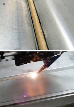
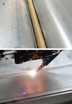
Diode laser brazing is a well-established method for joining galvanized steel sheets in series production of automotive bodies. Brazing optics, developed specifically for this application, are moved along the joint by means of robots. The laser beam is transported by a fiber to the optics, and copper silicon wire (CuSi3) is melted within the brazing process.
Key to the success of laser brazing technology, besides a stability that is similar to a weld, is mainly with the high aesthetic quality of the joints. Laser-generated brazing seams are known for their smooth, clean surfaces and junctions to the joining parts. This is visually appealing and it almost completely spares post-processing, allowing immediate painting after cleaning possible. Laser-based brazing enables such a unique impression of the joint that, unlike conventional joining techniques, cover parts and their storage and assembly can be saved.
However, laser brazing technology has not been able to meet—at least partially—the expectations placed on it. Automobile manufacturers have increasingly moved towards using hot-dip galvanized sheets in the body. Hot-dip galvanizing is more corrosion-resistant than the classical electro-galvanizing, so the changeover offers technical and economic advantages.
Laser brazing does not produce the usual results because of the new surface features of the sheets. In areas close to the joints, spatter increasingly occurs—especially micro-spatters—that can hardly be recognized at the beginning, but clearly appear after painting. The quality of the joint itself decreases, as it is rougher and often shows the so-called wavelets that, if excessive, can exceed the required joint appearance. These procedural difficulties have caused automobile manufacturers to seek alternative solutions from their distributors.
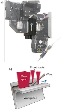
At that time, we had been testing brazing with a rectangular spot instead of the traditional round single spot. To produce a rectangular spot in a brazing optic, a homogenization module is put into a Scansonic ALO3 brazing optic (FIGURE 1a). Such homogenizers have been used for years by Laserline to create rectangular spots for hardening with laser powers up to 10kW.
Triple-spot module technology
We aimed to create a rectangular spot with a recess in which a wire could be supplied. This first geometry did not directly lead to the required success, but within a year we were able to develop (with several iteration stages) the present triple-spot module known as the optimized rectangle spot (OR spot) module. In this solution (FIGURE 1b), there are two smaller front spots positioned at the main spot that ablate the galvanization at the edges of the brazed seam. The main spot melts the lot, directly following a separate process, and creates the required joint.
The process is calmed by ablation of zinc at the edge area of the joint, such that spatters and wavelets are almost completely prevented. Doing so enables creation of smooth and clean joints.
Beam distribution in three beams by means of a triple-spot module within the brazing optics has many beneficial properties (FIGURE 2). To calm the brazing process described above, an exact arrangement of the spots to one another is necessary, while on the other hand, an exactly adjusted distribution of the laser power to the three spots is necessary. Different power distribution in the three spots is also needed, depending on the application (roof or tailgate) or different joint geometries. The patented triple-spot module offers the advantage of a stepless adjustable power distribution between the main spot and the front spots, and between these leading front spots. Furthermore, with this module, the space between the front spots can be subsequently adjusted. The position of the module within the tactile brazing optics directly behind the integrated swivel axis also has a special meaning. Since their introduction, the tactile brazing optics patented by Scansonic have been in use for some time now, making a significant reduction of seam errors possible.
The robot has limited path accuracy and components, and clamping techniques do not always bring the joint into exactly identical positions. So, the wire is used as a seam-tracking sensor by the optics, and the frontal telescopic arm is swiveled for seam tracking. After the swivel axis, the laser beam is redirected at a 45° mirror, and follows the wire. Because of the integration of the module behind the swivel axis, the triple spot created is always correctly oriented towards the wire. Therefore, the brazing process with robot and optics can be programmed as usual. If a triple-core fiber (also available commercially) is used to create a triple spot, the swivel axis must be left out. When using a swivel axis, and because of the 45° mirror, the front spots would turn around the axis of the main spot, which would lead to process fluctuations. With the triple-spot module, special fibers or lasers are unnecessary.
Laserline diode lasers are used for brazing by almost all large automobile manufacturers around the world. Diode lasers, with a beam parameter product of 60mm-mrad, are the standard lasers, and we have developed the triple-spot module for use with these lasers—so standard lasers with up to six exits can be used. Furthermore, standard fibers can be inserted via plug-and-play, which is advantageous if an older system is equipped with triple-spot modules. In most cases, the standard lasers already in use only need a revision of the optics. If further improvements of the modules are made, those already installed can be easily exchanged with newer ones.
Because of the variety of positive features, the triple-spot module, which was introduced at the beginning of 2016, has already entered automobile production. Now, the module is integrated into several series productions. The triple-spot concept offers a solution for brazing hot-dip galvanized sheets with the usual quality and production techniques.
Aluminum welding applications
Welding of aluminum, in addition to brazing, is the second most common application for diode lasers. Within the last five years, several dozens of diode laser systems with 4 to 6kW power have been installed in the field.
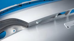
FIGURE 3 shows examples of welding on the exterior of tailgates. Part geometry, clamping techniques, and processes are similar to laser brazing on the exterior surface. However, welding of aluminum requires a smaller focal diameter of typically 0.6 to 0.9 mm to allow keyhole welding. Laser welding is also often used in structural parts. After welding, the seam is directly coatable and additional finishing is not required.
Tactile laser welding with triple spots
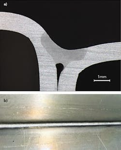
The typical aluminum welding process described previously is characterized by a round spot that is 0.6 to 0.9mm in diameter. The laser is delivered via a fiber with a 600μm core and focused onto the workpiece through a tactile process optic with a magnification of 0.9 to enable keyhole welding. FIGURE 4 shows a cross-section of a lap joint fillet weld with 1.6mm aluminum silicon (AlSi) filler wire, which is typically applied in the structure or non-visible areas of hang-on parts.
Tailored triple spot modules can be utilized if welding through or excessive root convexity needs to be avoided or if a class-A seam surface is required. This optimizes heat flow and therefore the surface and cross-section of the seam is improved. The operation principle is the same as explained in the brazing section above.
FIGURE 5 shows the results of linear-edge fillet welds on 5xxx aluminum test coupons with tailored triple spot geometry made in our application lab. The process window for a given robot and wire speed ranges from 3.8 to 4.6kW at a velocity of 4 m/min. While the main spot accounts for the welding process, the additional circular spots running in the front or back of the process smooth the seam. Thus, these tailored spot geometries allow combining the advantages of heat conduction and keyhole welding. One part of the spot opens up the keyhole, while the surrounding intensity profile guarantees a smooth weld comparable to a heat conduction process.
In FIGURE 6, a similar process is carried out on an outer skin roof coach joint. Tailored intensity profile and heat distribution allow for a very smooth and tight seam.
The fundamentals of laser aluminum welding are understood to a large extent, so further improvements tend to occur in the welding process' details—for example, spot geometries can be changed to optimized shapes. Diode lasers help to create added value in modern production lines' major automotive applications because they are robust, easy to operate, and highly modular.
DR. AXEL LUFT([email protected]) is Sales Manager, Global Automotive for Laserline, Mülheim-Kärlich, Germany; www.laserline.de.
