Technology has uses in welding thin sheets and dissimilar materials
JING-BO WANG
High-power and high-beam-quality solid-state lasers, such as the thin-disk laser and fiber laser, have made laser welding popular in manufacturing industries. More recently, kilowatt direct-diode lasers have become commercially available with beam quality competitive to thin-disk or fiber lasers [1-2] because of a laser beam combining method called wavelength beam combining, by which beam quality can be maintained without deterioration when power scaling. Replacing CO2 lasers, these solid-state lasers are becoming the main players in the field of remote laser welding.
Remote laser welding (RLW) is characterized by a long focal length and a fast-moving laser spot on a workpiece, generally by a pair of mirrors called a scanner [3]. The weight of the scanner is said to be over 30kg [4], making it necessary to use a heavy load robot. This article reports a newly developed Laser Processing Robot Integrated System Solution (LAPRISS) with a compact laser welding head for RLW, and shows several applications.
LAPRISS technology
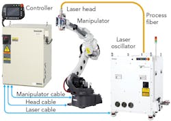
FIGURE 1 shows the main components and connection of this system, including a 4kW direct-diode laser scaled by wavelength beam-combining technology [1] and a newly designed trepanning type of laser welding head mounted directly on a robot manipulator. Robot motion and laser oscillation, including its power and irradiated laser pattern on the workpiece, are controlled by a robot controller.
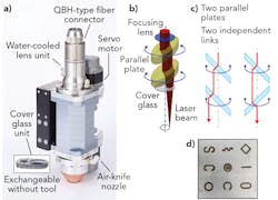
In the laser welding head, two parallel optical plates are driven independently by two servo motors to change the optical paths and form different types of irradiated laser patterns on a workpiece (FIGURE 2). The laser welding head is designed to weigh less than 5kg, making it possible to be carried with a light load robot.
From the typical irradiated laser patterns shown in FIGURE 2d, it is easy to consider that LAPRISS could replace resistance spot welding (RSW) or arc welding by using a circle- or line-shaped welding bead. Among the many merits of remote laser welding, LAPRISS can decrease cycle time when replacing RSW, and increase gap tolerance in thin metal sheet welding.
Decreasing cycle time
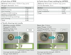
Cycle times by RSW and LAPRISS were evaluated on 0.8mm-thick mild steel, with the nugget diameters of RSW and the circle diameter in LAPRISS both set to 4mm. FIGURE 3 shows welding times of each action and tensile shearing test results, where the average times for welding are 2.85 and 0.675 sec in RSW and LAPRISS, respectively, and the cycle time of LAPRISS is one-quarter that of RSW.
Assuming, for example, that the total number of welding spots in a car body is 3500–7000, total welding time could be reduced from 10,000–20,000 sec to 2400–4800 sec. There are no differences in tensile shearing strength between RSW and LAPRISS—both of the joints fractured in the base metal near the heat-affected zone (HAZ).
Increasing weld gap tolerances
When using laser welding in thin sheet applications like automotive manufacturing, many parts are produced by shearing or press. So, increasing the gap tolerance becomes important, especially when joining high-strength steel parts because of their large spring-back during the press process [5].
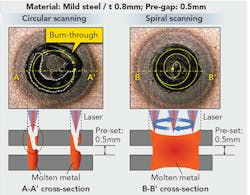
One method to compensate for wide-gap weld tolerance is spiral-scanning the laser beam on a workpiece from one point and then scanning it to draw a circle, with the circle diameter increasing gradually. During spiral scanning welding, the robot stops at one point and after finishing one weld, the robot moves to another point.
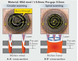
FIGURE 4 shows welding results with circle scanning and spiral scanning. In the case of circle scanning, burn-through occurred because of the shortage of molten metal. The maximum gap tolerance was only 0.3mm. On the other hand, the maximum gap tolerance of spiral scanning welding reached 0.5mm. Spiral scanning welding is useful in replacing RSW because the cycle time can be reduced by 25%.
Spin scanning welding
This method involves irradiating a laser beam on a workpiece and then scanning it to draw a circle with a same diameter during robot motion. The irradiated laser track on a workpiece resembles a projection of spring on a plane. The size of the molten pool is determined by the scanning circle diameter by changing this circle size, so many weld beads with different widths can be obtained.
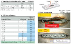
Spin scanning welding was evaluated in a butt joint with 0.8-mm-thick mild steel. The laser spot on the workpiece was set to the contact surfaces of two plates, or with an offset of 0.2mm perpendicular to the welding direction.
FIGURE 5 shows welding conditions and test results. When a pre-gap is 0mm, the permitted offset was only 0.2mm by conventional laser welding (line), but it could be increased up to 0.5mm with spin scanning welding. When a pre-gap increases to 0.2mm, the permitted offset was 0.9mm by spin scanning welding, which is nearly 9X that of conventional laser welding (0.1mm). Spin scanning welding is useful in replacing arc welding, and the weld speed can be increased by 2–3X.
Prospective future applications
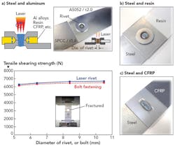
In addition to welding thin metal sheets, LAPRISS can also be used for joining dissimilar materials to produce a lightweight structure design, for example, in the automotive industry. A laser rivet process is proposed to replace conventional thermal joining processes, where the main problem is the formation of intermetallic phases from different alloy elements [6].
FIGURE 6 shows the principle of the laser rivet and a sample for joining steel to aluminum, generally considered difficult or impossible by conventional thermal processes. This laser rivet process may also be useful for joining steel and other non-metal materials like resin and carbon fiber-reinforced plastic (CFRP).
REFERENCES
1. R. K. Huang et al., "Direct diode lasers with comparable beam quality to fiber, CO2, and solid state lasers," Proc. SPIE, 8241, 824102 (2012).
2. J. Hecht, "Beam combining cranks up the power," Laser Focus World, 48, 6, 50–53 (Jun. 2012).
3. M. Grupp, T. Seefeld, and F. Vollertsen, "Laser beam welding with scanner," Proc. LIM, 2, 375–379 (2003).
4. T. Higuchi, J. Jpn. Weld. Soc., 77, 25–28 (2008).
5. T. Yoshida, E. Isogai, K. Sato, and K. Hashimoto, Nippon Steel Tech. Rep., 103, 4–10 (2013).
6. E. Schubert, M. Klassen, I. Zerner, C. Walz, and G. Sepold, J. Mater. Process. Technol., 115, 2–8 (2001).
Dr. JING-BO WANG([email protected]) is with the Engineering Department in the Thermal Fabrication System Business Unit of Panasonic Smart Factory Solutions; http://business.panasonic.com/solutions-smartfactorysolutions.
