Since the invention of lasers, manufacturers have continuously innovated, creating unique capabilities that improve processing throughput and quality, increase production yields, and, ultimately, support corporate growth and profit across widely diverse industries. In some cases, the value proposition of using a laser is relatively straightforward, such as eliminating costly consumables when milling hard materials or increasing solar panel efficiency with narrow and dense isolation scribes. In other cases, often as a result of unique light-matter interaction, the benefits are less straightforward and may arise by enabling new processes. This is often the story when it comes to processing transparent materials, glass in particular, with ultrashort-pulse (USP) lasers.
USP lasers have carved out a strong niche in the world of glass processing, in large part due to the nonlinear material interactions they induce. Compared to longer pulse widths or continuous-wave (CW) radiation, bundling a given amount of energy into an ultrashort femto- or picosecond pulse width will result in unique phenomena, such as self-focusing and multiphoton (and other nonlinear) absorption, all in an otherwise highly transmissive and passive material. Once absorption of light occurs, structural modification of the material is possible and the short time scales over which a pulse’s energy is deposited ensures a minimal amount of heating, melting, cracking, etc. In practice, a focusing lens is used to precisely control where nonlinear absorption and structural modification occurs.
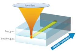
In some scenarios, a certain amount of heating may be useful, and this too is possible with ultrashort pulses. Ultrashort pulses have been tightly focused in glass and applied at a high pulse repetition frequency (PRF), resulting in heat accumulation and controlled, localized melting of quasi-spherical volumes below the surface, in the bulk of the glass. Early on, this paired phenomena of nonlinear absorption, coupled with high-PRF heat accumulation, was used to fabricate optical waveguides in bulk glass, since the melt/freeze cycling of the glass resulted in a spatially varying density and hence varying refractive index. It was also discovered that the same controlled, localized melting could also be used to fuse together two glass plates, if the plane of focus was positioned at the contact interface of the materials. While early work was done exclusively with femtosecond pulses, researchers have since discovered that energetic, high-PRF picosecond pulses are similarly effective. Figure 1 illustrates how the glass materials are arranged relative to the laser beam for laser through-transmission welding.
Bonding glass to glass or other material types such as metals is useful in a variety of industries, including consumer electronics, microfluidics (“lab-on-chip”), micro-optics assembly, and medical device packaging. Using adhesives is often problematic due to long cure times, aging, and outgassing issues. Adhesiveless bonding techniques, such as anodic bonding, also have downsides. For anodic bonding, candidate materials are somewhat limited, and they are subjected globally to high temperatures and electric fields for extended periods of times. With a laser-based microwelding approach, advantages include a lack of additional intermediary materials as well as high process localization, allowing processing adjacent to heat-sensitive components (electrical, polymeric, etc.). With these advantages in mind, MKS Spectra-Physics (Santa Clara, CA) laser applications engineers set out to test a high-power industrial picosecond pulse infrared (IR) laser (IceFyre 1064-50 picosecond laser) for through-transmission microwelding of glass-to-glass and glass-to-aluminum plate materials.
Given that tightly focused beams combined with high PRFs are known to work well for such a process, a fixed optics system with a short focal length asphere objective (0.5 NA) and a range of multimegahertz laser PRFs were used throughout the tests. Processing at higher numerical apertures is possible, but the reduction in working distance would further limit the potential to process thicker materials and deeper welds.
Glass-to-glass through-transmission microwelding
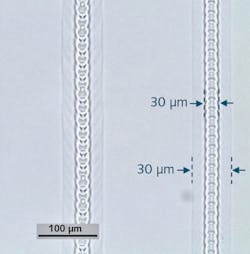
In the case of glass-to-glass welding, two glass plates (1-mm-thick soda lime microscope slides) were placed in optical contact with each other, ensuring no air gaps or contaminants were present to interfere with the process. The focused beam, calculated to have a ~2 µm 1/e2 diameter, was placed at the interface of the two plates and the sample was translated laterally using a Newport precision XY stage system. Parametric test variables included average power, PRF, and scan speed; evaluation and optimization were based on welded line continuity and minimization of glass fracturing. Best results were achieved at an average power of 5 W, PRF of 10 MHz, and sample translation speed of 25 mm/s. Weld structure and quality are revealed via optical microscopy, with an image from a top-down perspective presented in Figure 2.The welds are very faint and not visible to the naked eye. Under the microscope, we see a well-defined central modified region ~30 µm in width, as well as a much fainter outer region extending ~25 µm on either side. The inner region has a periodic modulation in the melt pool at a pitch of ~20 µm. This is much larger than the pulse spacing (<1 µm) in the material, and is believed due to a feedback process in which plasma and/or melting momentarily distorts the beam focus, thereby reducing the nonlinear absorption in the material, which reduces plasma/melt and allows reversion back to ideal focus (and repeating along the motion trajectory). The large outer modified region is comparatively not modulated, indicating that a stable, steady-state thermal equilibrium is maintained throughout the trajectory.
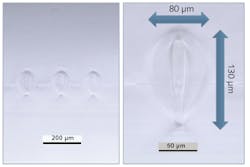
A cleaved and polished cross-section of the weld sample provides more detail on the modified regions within the glass (see Fig. 3).The cross-section inspection reveals that the overall modification region is elongated, consistent with existing literature. Both the inner, stronger modification region and the more subtle outer area are smooth and devoid of fractures. In addition, there is a clear, well-defined boundary between the two regions. The images also demonstrate the glass is fused along the interface at the point of each weld with no discernable disruption where the once-molten feature transits the interface.
Glass-to-glass spot microwelding
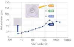
In some manufacturing processes, a spot microwelding process may be preferred to a continuous line weld. To develop such a process, testing was performed in the bulk of a single glass plate, rather than at the interface, as this is believed to be representative of welding behavior between optically contacted glasses. For the stationary weld features, the laser parameters were re-optimized and best results were achieved using lower power and PRF values compared to those for linear microwelding. In particular, the power levels for successful welding were in the 1–2.5 W range and the optimal PRF was found to be 1 MHz. With these settings, highly symmetric melt regions were formed, with size being dependent on both the average power and the number of applied pulses. In Figure 4, melt diameter vs. number of pulses is plotted for ~1 W average power for a range of pulse counts, with additional data for higher power levels at a fixed pulse count of 125,000 pulses (this equates to a 125 ms exposure time at 1 MHz PRF).The data shows that the melt diameter is well behaved for 1 W power and up to 125,000 pulses, beyond which further growth becomes erratic. Further growth, however, can be achieved by increasing the average power, with approximately 25 µm of diameter growth per 0.5 W power increment. Such well-controlled growth is indicative of both a robust processing regime and stable laser performance. When viewed through the microscope, the smoothness and overall quality of the features is apparent. Included in Figure 4 are microscope images of two melt features generated at opposing extremes of the parameter space explored, spanning a range of diameters from very small (16 µm) to very large (140 µm). While very different in size, both features exhibit the same excellent quality.
Glass-to-metal through-transmission microwelding
A laser-based microwelding process for bonding glass to metal could be very valuable to industries such as mobile device manufacturing. The historical trending is clear—smaller and more elegant devices devoid of superfluous materials such as adhesives and mechanical fasteners or constructs have widespread appeal to consumers and manufacturers alike. In this spirit, a series of experiments aimed at through-transmission laser microwelding of glass to aluminum plate was carried out. The laser and setup were identical to that used for glass-to-glass welding, with one notable exception: because glass and aluminum cannot be optically contacted, a mechanical clamping apparatus was implemented to hold the two plates in close contact during laser irradiation.
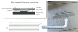
Processing parameters for glass-to-aluminum welding were found to differ significantly from those for glass-only welding. Since the focus is placed at the surface of the aluminum where the laser energy is strongly (and linearly) absorbed, the optimal average power was found to be much lower at ~0.6 W. The PRF was also significantly reduced, to 800 kHz, for the same (glass-to-glass) translation speed of 25 mm/s. To facilitate ease of inspection and ensure strong bonding, large welded regions were fabricated by implementing a parallel line raster pattern process, with a line spacing (pitch) of 50 µm and overall dimension of length, width = 20 mm, 3.5 mm. Figure 5 contains a schematic of the clamping apparatus as well as diagrammatic representation and an actual welded sample using the parallel line raster process.Although the digital macro photo of the welded region does indicate some apparent darkening, the polished texture of the aluminum is clearly maintained, as is some level of its characteristic reflectivity. Importantly, the individual weld tracks are not visible, and the result is the appearance of a uniform, bonded area with no visible cracking.
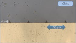
Cross-sectioning of the glass/aluminum welds reveals more interesting details of the weld structures (see Fig. 6). The welds appear as raised ridges protruding from the aluminum into the glass, and there is no visible gap between the two materials and no sign of infiltration of the melt into the unwelded regions along the interface.For these microwelding experiments, testing the weld strength was beyond the project scope. However, some indication of the strength was gleaned by forcefully separating the welded plates. The result was promising, with large sections of glass cleaving off from the main plate and remaining fused to the aluminum, indicating a strong bond between the two dissimilar materials.
Summary and outlook
Lasers continue to surprise on the upside when it comes to improving and enabling industrial processes. This is especially true for USP lasers, with their ultra-high intensities and the accompanying nonlinear material interactions. As processing transparent materials such as glass continues to grow in industrial manufacturing, this trend is expected to continue. Here, we have reviewed experimental results for through-transmission laser microwelding of glass-to-glass and glass-to-aluminum. Using the MKS Spectra-Physics IceFyre laser, we have demonstrated well-controlled processes that lead to high-quality results. The simplicity and flexibility of such processes have much to offer for a range of applications, and it appears high-power, high-PRF picosecond technology is well suited for the task.
ACKNOWLEDGEMENT
MKS Spectra-Physics and IceFyre are registered trademarks of MKS Instruments.
