RANDALL WILCOX
Piezoelectric devices have the unique property of generating a voltage when a pressure is applied, as well as the inverse property, expanding when a voltage is applied. Laser and photonics applications generally rely upon the latter: converting a voltage to a very accurate displacement for processes such as alignment of a fiber to a device or waveguide, control of the tilt of a harmonic crystal, making laser-cavity length adjustments, or scanning a tunable diode laser.
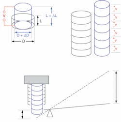
When a voltage is applied to a cylindrical piezoelectric element, the cylinder increases in length (and decreases in diameter). This expansion is a percent of the total length L of the cylinder. And because the total length of a piezoelectric element is relatively small, the resulting change in total length is much smaller (in the nanometer range), which is good for applications that need high resolution across relatively short displacements.
To increase the total travel and retain similar nanometer-scale resolution, piezoelectric elements can be stacked and voltage applied to elements in parallel such that the total length increases, yielding displacements in the micron range.
One way to increase the travel further is to stack piezoelectric elements and add a leveraging system. Travel can extend to the 20, 100, or even 200 µm range. Such leveraged displacements apply less force, but they are still generally suitable for applications such as automated alignment of fibers and waveguides (see Fig. 1).
Fiber alignment
In stacked or leveraged configurations, additional physical parameters to be considered include hysteresis and temperature effects. Hysteresis increases along with length of travel, and piezoelectric elements also have high coefficients of thermal expansion. Such potentially problematic properties can be reduced significantly, however, with the use of feedback systems. For example, if an automated alignment system relies on a photodiode signal and dithering to determine the direction of correction, hysteresis may not come into play on the final alignment if the hysteresis effect is significantly lower than the final alignment tolerance.
An example of such a photodiode feedback for optimizing alignment is the Elliot Scientific (Harpenden, England) DALi system that can be used to align fiber-optic single-mode cores down to 1 µm in diameter. Once a user has manually adjusted the system to receive “first light,” the DALi system can then take over and make small adjustments to determine the appropriate direction for optimizing the signal to the photodiode and will then continue steps in that direction until the maximum signal is achieved.
Once a device is aligned in the x-, y-, and z-axes, if an angular adjustment is required, such as aligning a second channel, the fiber will also translate during the angular adjustment, enabling the DALi to keep translation axes aligned. The 200 µm piezo actuators can also provide a larger scanning area to automatically detect “first light.” The device is intended to improve productivity in manufacturing and R&D groups working with planar waveguides, splitters, fiber pigtailed devices, optical switches, and semiconductor optical amplifiers (SOA).
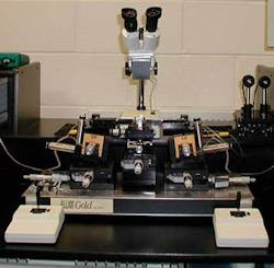
Some of these configurations, such as the planar waveguide or the SOA, require alignment of the input and the output faces of waveguides, which, even though flat, may not lie perpendicular to their respective longitudinal fiber axis. Instead, such input and output surfaces can form “wedge” angles with their longitudinal fiber axis, which can make fiber alignment more difficult. The solution is to design a test fixture with wedges at appropriate angles such that the translation adjustments are made with input and output faces of adjacent components parallel to each other (see Fig. 2).Laser-beam control
Piezoelectric elements play an important role in line-narrowed diode lasers. A diode laser with nanometers of bandwidth can be made into an extremely narrow-linewidth laser with a grating as part of an external-cavity configuration. Rotating the grating provides precise wavelength tuning. Course adjustments are made with a screw and a piezoelectric element on the end of the screw is used for the fine control of the grating position. The wavelength of the laser can then be scanned or locked to a particular reference such as a cesium or rubidium gas cell, as in laser trapping and cooling experiments.
If a laser beam is being deflected, there are techniques for stabilizing the beam pointing using piezoelectric technology such as the beam-pointing stability system from Laser-Laboratorium Göttingen (Göttingen, Germany). The system makes use of a patented detector that allows simultaneous monitoring of the near field and the far field of the laser beam to be stabilized (see Fig. 3). Automated readjustment after a lateral or angular movement of the beam position is achieved by use of a comprehensive computer program, which allows determination of the beam-pointing stability in accordance with the ISO standard 11670.
In addition, piezoelectrics can be used simultaneously with acousto-optics (which convert acoustic energy into a change of index of refraction) for beam deflection. The piezoelectric element generates the acoustic signal for the acousto-optic element. Applications include Q-switching and other types of beam deflection.
Synchronizing ultrafast laser pulses-as in applications in which the user would like to synchronize two ultrafast oscillators such as coherent anti-Stokes Raman-scattering (CARS) microscopy, pump-probe experiments, or to synchronize the output of an ultrafast oscillator to another system such as a linear accelerator-can present significant challenges. Each pulse in a modelocked Ti:sapphire ultrafast oscillator operating at a repetition rate of 80 MHz is separated by 12.5 ns or approximately 3.75 m, and if the pulse width is 200 fs, the pulses are each approximately 60 µm long. Overlaying 200 fs pulses within 10% requires 20 fs resolution. At 80 MHz, this translates to mechanical tolerance of 35 nm over a distance of 3.75 m.
Such ultrafast oscillators are synchronized to each other or to external systems using phase-locked loops and through adjusting cavity lengths by moving end mirrors with high-speed piezoelectrics. Such techniques enable matching of repetition rates and control of phase to overlay pulses. Phase control also provides a mechanism for scanning pulses in time to optimize the flow of experimental processes.
Ultralong displacements
What about travel longer than 200 µm with piezoelectric elements? There have been many configurations implemented and commercialized for extending the travel of piezoelectric elements. These include descriptions such as “slip-stick,” “inch worm,” “ratchet,” and others. The bottom line is that many products are now offered that can extend the piezoelectric effect into the millimeter range, while retaining resolution of piezoelectric elements in the nanometer range.Adding a measurement system to these long-travel piezo stages can create a closed-loop system in which the user can input a position rather than a number of steps, and the system will respond by driving to a specified position within a specified tolerance. Another benefit to piezoelectric elements, stacks, and other extended-travel configurations is that they can be prepared for vacuum compatibility, and even cryogenic compatibility down to 4 K. Long-travel piezo translation stages are often used in laser delay lines (see Fig. 5). A stage that maintains precisely stable yaw or pitch angles can be critical for such applications. And a piezoelectric beam pointing stabilization system as described earlier might be used to compensate for any unwanted motion.
RANDALL WILCOX is engineering manager at Lightspeed Technologies, P.O. Box 110161, Campbell, CA 95011-0161; e-mail: [email protected]; www.light-speed-tech.com.


