A high-quality, high-speed micromachining process is important for implementing a cost effective solution on a manufacturing machine. Use of lasers for micromachining has grown steadily over the years, and by 2015 laser micromachining is expected to be a $752M market.1 In recent years there also has been rapid advancement in laser technology. The energy available per pulse and the pulse repetition frequency (PRF) of diode-pumped solid-state (DPSS) nanosecond ultraviolet (UV) lasers have increased dramatically. Efficient use of the available energy from a laser source is important to achieve maximum material removal and minimal thermal damage for any laser micromachining application.
The use of the optimal energy density, or fluence (J/cm2), for material removal is especially important for short pulse-width lasers. Compared to longer pulse widths, a shorter pulse results in shallower thermal penetration depth, which means smaller heated volume and hence less residual heat-affected zone (HAZ) in the material. This allows for a controlled and precise micromachining process, which is why many in the industry continue to choose short-ns pulse width DPSS lasers for their most quality-stringent applications.
At the same time, there is always the desire for fast processing, and although short pulse widths can result in fast throughput, improper process optimization can result in comparatively less material ablated due to the shorter heating depth. While it is tempting to simply increase the pulse energy (and hence fluence) to gain throughput, this runs the risk of eliminating the quality advantage inherent in the short pulse width. Rather, one should consider that along with the smaller heated volume of the short pulse width comes a lower ablation threshold—that is, for the same irradiated area (i.e. focus spot size), shorter pulse widths require less energy input to initiate material removal. Considering this, it follows that with enough flexibility in the laser and the machining setup, the available pulse energy can be shaped in space and time in such a manner that high-quality and high-throughput can be achieved in tandem.
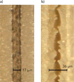
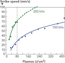
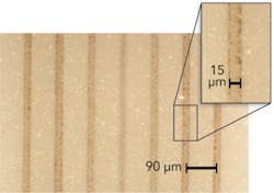
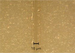
The intuitive tendency for achieving higher machining speed is to increase fluence, especially when higher energy is available from the laser. However, this is an inefficient way to achieve higher machining speed and furthermore it may come with the penalty of reduced machining quality. This is clearly illustrated by the data shown in FIGURES 1 & 2. FIGURE 1 shows the scribe speed required at different fluences to achieve 30 μm scribe depth in alumina ceramic. The data was generated using Spectra-Physics Pulseo 355-20 DPSS Q-switched laser with short pulse width of <23 ns. The data shows that 3× increase in the fluence results in only 2× increase in the scribe speed. This clearly demonstrates inefficient machining at excessive fluence levels in which a reduced portion of the pulse energy causes material removal while an increased percentage goes towards material heating. Excessive heating and associated thermal affects are evident from the microscope pictures shown in FIGURE 2 (a) and FIGURE 2 (b) which shows more molten material within the scribe and hence wider scribe width generated at higher fluence.One of the limitations of operating at a lower fluence is that while the processing is more efficient on a per-joule basis, the actual amount of material removed is in fact reduced. All else being equal, this will limit throughput. Furthermore, low-fluence processing is not consistent with the higher pulse energies that are available with today's newest lasers. To fully utilize such pulse energies, a process scheme must be defined that allows operating at a lower fluence but at the same time achieving higher processing speed with high quality.
The simplest way to operate in the low fluence regime without compromising throughput, and thereby take best advantage of the higher available laser powers, is to operate the laser at a higher PRF. For a typical frequency-doubled or -tripled (e.g. 532 or 355 nm) DPSS Q-switched laser, the output power decreases with increasing PRF. Hence the energy per pulse and thus the fluence available at higher PRF is lower; however, faster machining speed is achieved due to higher PRF. In essence there is less material removed per pulse, but the increasing pulse rate in time more than compensates for this, resulting in a net process efficiency gain.Operating the laser at a higher PRF is the most straightforward way to introduce fluence management into the process. But this higher-PRF operation usually results in lower laser output power. One might consider that if the fluence could be managed in such a way that the laser can be operated at its point of maximum output power, this might result in the highest possible throughput for that particular laser system. This can be achieved by using spatial beam shaping techniques such as elliptical beam processing and laser beam splitting. Both of these techniques allow the laser to be operated at the PRF corresponding to maximum output power and thus the maximum possible throughput is achieved, although with the tradeoff of added complexity and cost in the optical system.
As a first example we study these spatial fluence management techniques in scribing alumina ceramic material.
Machining using an elliptical laser beam
Elliptical beam processing is useful for generating deep, narrow scribes at high speeds. For this purpose, the beam is shaped to have a minor axis diameter to achieve a target scribe width. With this restriction in place, it then becomes necessary to elongate the beam (in the direction of the scribe) to the point of optimal fluence. With a constant minor axis, elongation of the beam results in a linear reduction in fluence—i.e. doubling the length of the beam halves the energy density. The exact optimal major axis diameter depends on the exact scribe goals. Besides the material type, the targeted scribe depth is also a factor, with deeper scribes requiring higher fluence (and hence a shorter major axis) compared to shallower scribes.
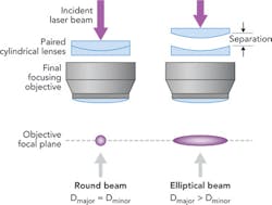
Generating an elliptical beam from the typical round Gaussian output laser beam typically requires the use of one or more cylindrical lenses. One convenient optical configuration uses a set of paired cylindrical lenses having equal but opposite focal lengths - that is, one lens is plano-convex and the other is plano-concave, but each non-planar side has the same radius of curvature. When the pair is located just before the final focusing objective, the separation of the lenses can be varied to adjust the ellipses major axis while the minor axis remains fixed. When the separation is zero, the beam retains its original round shape since it is essentially passing through a solid block of glass; as the separation is increased, the beam becomes increasingly elongated (FIGURE 5).The main advantage of using an elliptical beam is that the high energy available from the laser is spread spatially to achieve the optimal fluence at the surface. Also, it is possible to maintain desired narrow kerf width along the minor axis and vary laser fluence by changing the major axis.
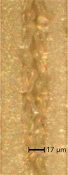
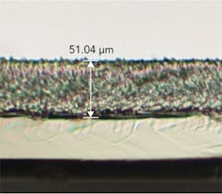
Using an elliptical beam with ~10 μm minor axis and ~225 μm major axis diameter and ~170 μJ energy available from laser, which provided 19 J/cm2 fluence at the surface, we were able to generate 30 μm deep scribe in alumina at a speed of 200 mm/s. Scribe quality achieved, as shown in FIGURE 6, was also high with minimal HAZ.Machining using laser beam splitting
Traditionally, beam splitting is used to distribute a single high-energy laser beam into multiple beams for simultaneous processing of either different materials or different areas of the same material. In such scenarios, each of the split beams has its own beam path and final delivery optic - a focusing objective, for example. Recently, designers have applied the split beams more locally to the material, with each beam having a shared post-split optical path. Even with the same final delivery optics, the beamlets can be used sometimes to generate a number of identical but spatially separated features in a small, localized area of the material.2 In other cases, the beamlets are applied to the material in close enough proximity such that a single, high-quality feature is generated with maximum throughput.3 The beamlets can be generated with novel refractive optics such as micro-lens arrays or purpose-built diffractive optical elements (DOEs). Whatever the method, the end goal is to split the high energy available from the laser into "N" different beamlets; in the ideal scenario, each beamlet will have the optimal low fluence value for achieving best process efficiency.Conclusion
To achieve maximum material removal with minimal heat affected zone, managing the laser fluence at the sample is of critical importance. Multiple fluence management techniques can be used to achieve optimal system throughput - each with particular tradeoffs with respect to performance, complexity, and cost. In some cases it may be best to simply adjust the laser PRF to gain efficiency alongside the quality benefits of applying the optimal fluence. In other cases, spatial fluence-management techniques described here—elliptical beam shaping and laser beam splitting—can be used to more fully realize the throughput potential of a given laser source, but with added complexity and system cost. Careful application of such techniques to effectively manage the high energy and high PRF available from today's Q-switched DPSS lasers will likely benefit almost any material processing application.
References
1. "The Worldwide Market for Lasers Market Review and Forecast 2012" report, Strategies Unlimited, 5th Edition (2012).
2. Maik Zimmermann, et. al., "Combination of a micro lens multi spot generator with a galvanometer scanner for flexible parallel micromachining of silicon," Proceedings of SPIE Vol. 8243 (2012).
3. Jeroen van Borkulo, et. al., "Enabling Technology in Thin Wafer Dicing", ECS Transactions, Volume 18, Issue 1, pp. 837-842 (2009)

