Ronald D. Schaeffer and Gabor Kardos
Some cleaning techniques affect the quality and financial impacts of laser processing
In many manufacturing operations, cleanlinessof laser processed parts is of paramount importance, especially when manufacturing medical devices, semiconductor devices, and aerospace components. Even when performing “clean” laser processing at ultraviolet (UV) wavelengths and using short pulses, some debris is usually formed during the laser process. The best possible approach is to minimize the amount of debris generated (see “Toward debris-free laser micromachining,” ILS, January 2008, p. 16) during the laser process. Even in the cases cited, however, some amount of post-laser processing usually needs to be done, such as removing sacrificial coatings or drying wet processed parts. Here we review some techniques that are used as post-laser cleaning techniques.
Note that cleaning parts, especially medical parts, is a somewhat risky business for a contract manufacturer as it may not always be apparent that the post-laser cleaning techniques will not cause bigger problems than the debris. To avoid incompatibilities, contract manufacturers will normally not clean laser processed parts unless there is a clear understanding with the customer concerning the techniques used. Post-laser cleaning techniques must be well documented, and established procedures must be followed rigorously to assure the proper end product.
Physical scrub
The simplest and most economical method of part cleaning is a simple physical scrub. This is a contact method, so extreme care must be taken regarding the scrub solution (if any is used), the scrub tool, the aggressiveness of the scrub, and the time of scrub. Q-tips, cleanroom wipes, or soft brushes are normally used on small and delicate parts manufactured using laser micromachining. Acetone, methanol, ethanol, or water (perhaps with a cleaning surfactant) can be used as the solvent. The cost for using this technique, aside from labor, is low.
null
null
Chemical baths
An ultrasonic cleanerndash;an ultrasound device usually operating from 15–400 kHzndash;is used to clean delicate items like jewelry, optics, precious metals, surgical instruments, and electronics. In an ultrasonic cleaner, the object to be cleaned is placed in a chamber containing a suitable ultrasound conducting fluid (an aqueous or organic solvent, depending on the application). In aqueous cleaners, the chemical added is a surfactant that breaks down the surface tension of the water base. An ultrasound-generating transducer is built into the chamber or may be lowered into the fluid. It is electronically activated to produce ultrasonic waves in the fluid. The main mechanism of cleaning action is the energy released from the creation and collapse of microscopic cavitation bubbles, which break up and lift off dirt and contaminants from the surface to be cleaned. The higher the frequency, the smaller the nodes between the cavitation points, which allows for more precise cleaning. The bubbles created can be as hot as 10,000° with 50,000 lbs psi pressure, but are so small that cleaning and removal of dirt is the main result.
Ultrasonic transducers work by rapidly changing size when excited by an electrical signal, creating a compression wave in the liquid of the tank. These compression waves actually “tear” the liquid apart, leaving behind a “void” or “partial vacuum bubble”. When these “bubbles”ndash;and there are many millions of them in an active ultrasonic tankndash;collapse, they do so with enormous energy. When sufficient energy is built up in the bubble or cavitation, it collapses violently. The transducers are usually composed of piezoelectric material (for example lead zirconate-titanate or barium titanate), and occasionally are made of magnetostrictive material (for example nickel or ferrite). The often harsh chemicals traditionally used as cleaners in many industries can be reduced or eliminated with the introduction of ultrasonic technology.
Devices for home and hobby use are readily available, and may cost as little as $50. Typical units for production, however, are priced in the range of a few hundred to a few thousand dollars, and the operating costs are very low, assuming there is no need for exotic liquids.
Electropolishing
Typically, the metal workpiece is immersed in a temperature-controlled bath of electrolyte and connected to the positive terminal (anode) of a DC power supply, with the negative terminal being attached to an auxiliary electrode (cathode). A current passes from the anode, where metal on the surface is oxidized and dissolved in the electrolyte. At the cathode, a reduction reaction, normally hydrogen evolution, takes place. Electrolytes used for electropolishing are most often concentrated acid solutions with a high viscosity such as mixtures of sulfuric acid and phosphoric acid. Other electropolishing electrolytes reported in the literature include mixtures of perchlorates with acetic anhydride and methanolic solutions of sulfuric acid.
To achieve electropolishing of a rough metal surface, the protruding parts of a surface profile must dissolve faster than the recesses. This behavior, referred to as anodic leveling, is achieved by applying a specific electrochemical condition, most often involving a mass transport limited dissolution reaction. A second condition for achieving polishing is that surface heterogeneities due to crystal orientation in a polycrystalline material are suppressed and that no pitting occurs. These conditions, often associated with surface brightening, are usually fulfilled with the above-mentioned polishing electrolytes and with proper process control.
In electropolishing, there is a very significant preference to the removal of any high spots on the metal surface. This means that the dimensions of the high spots are changed drastically while the dimensions of the lower spots are changed very little. This creates a smoothing effect to the metal surface. It also means that, by nature of the process, the total amount of dimensional change required to obtain the polish effect is very small. Dimensional reduction of the workpiece is on the order of 0.00025 in. Electropolishing has many applications in the metal finishing industry because of its simplicity and because it can be applied to objects of complex shape. Typical examples are electropolished stainless-steel surgical devices.
Plasma etch
Using plasma to desmear eliminates an entire wet process line, reduces chemical disposal cost, and reduces water usage and treatment costs. Labor costs are lowered as well because there are no baths to maintain. With plasma etching, the panels are placed in a vacuum chamber, and gas is introduced and converted to reactive plasma by a power supply. The plasma reacts at the panel surface and volatile by-products (resin smear) are removed by the vacuum pump.
The addition of relatively inert gases, such as nitrogen or argon, stabilizes the plasma and controls the rate of ionization. Reactive oxygen species oxidize organic contaminants on the surface, creating volatile species that are pumped away. Etch rates are increased by providing more reactive species in the form of fluorine such as F2, CF4, or CHF2.
null
null
null
Permanganate desmear
During laser drilling of a printed circuit board, for instance, resin becomes heated, resulting in the melting and smearing of the epoxy-resin base material across the inner-layer copper surfaces within the hole barrel to which subsequent through-hole plating must connect. If not corrected, the smear would constitute a dielectric layer between the inner-layer copper surfaces and the plated copper, and the circuit would be defective.
The desmear process is often grouped and sometimes confused with etchback because similar or identical chemistries can be used to perform both functions. Desmear is simply the removal of smeared epoxy-resin by-products from copper surfaces within the hole barrel or left-over residue on conductive surfaces to facilitate an electrical connection with copper.
Currently the most widely used chemistry is sodium or potassium permanganate when significant etchback is not required or specified. Permanganate-based systems remove a thin layer of epoxy-resin (typically less than 1 mil) and smear and are quite adequate for desmear-only applications.
Results and conclusion
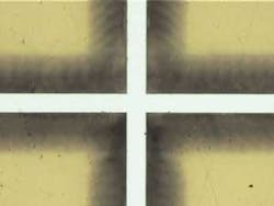
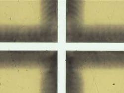
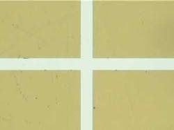
Let’s take a look at some laser etched (and in some cases cleaned) parts, with all kerf widths and hole diameters approximately 100 microns. Figure 1a shows a piece of polyimide about 5 mils thick that has been laser etched with a crosshair of about 100 microns kerf width. This part has been photographed directly from the laser, and debris is clearly evident. Figure 1b shows the same part after gentle wiping with IPA. Note that the part is very clean.
Figure 2a shows a piece of glass that has been laser etched and photographed with the debris being very evident. A gentle ultrasonic cleaning was performed and the result is shown in Fig. 2b. Note that the debris is almost entirely removed, but there remains chip out of the brittle glass. It is sometimes possible to reduce this effect, but it is difficult to eliminate it without either using a sacrificial layer or doing an additional post-laser grinding process.
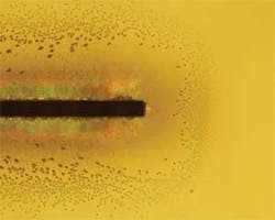
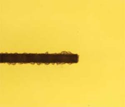
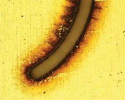
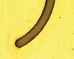
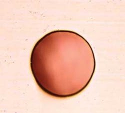
Figure 3a shows a piece of stainless steel that has been laser etched and photographedndash;again the debris is evident. Figures 3b and 3c show the same part after cleaning with an IPA wipe and with ultrasonic cleaning, respectively. It is evident that most of the debris can be removed, however, this material shows another effect even after cleaning that may be undesirable: recast. The cleaned parts clearly show the melted/recast material around the cut and no gentle cleaning will remove this. In order to effectively remove this recast, a gentle electropolish is necessary. Figure 3d shows a stainless-steel part that has been electropolished after laser drilling. Note that no high spots are evident on this photograph; through the electropolishing process, the high spots have been preferentially removed.
Space does not permit an exhaustive review of all the post-laser cleaning techniques available, but the above gives an indication of some of the more common methods in use. Others such as CO2 “snow blasting,” “lint tape” removal, etc. also exist and can be used to enhance the quality of laser processed parts.
Dr. Ronald Schaeffer and Gabor Kardos are both with Photomachining (www.photomachining.com) in Pelham, NH. In addition to being CEO of this company, Ron ([email protected]) is also a valued, frequent Contributing Editor to ILS.
