Laser drilling improves turbine engine performance
Water-jet laser guidance technology minimizes heat damage to parts
NITIN SHANKAR
When officials with GE Aviation and GE Power talk about big investments in new technology, they prefer describing it as a calculated but necessary risk. GE Aviation, an operating unit of GE, has an industrial backlog of more than $150 billion. This translates into more than 15,000 jet engines, most of which will be supplied to Airbus and Boeing. As a result, jet engine developers are looking into improved designs and new materials for improving performance.
Increasingly, laser technologies are overcoming the limitations of conventional machining in processing turbine components. For example, lasers can pierce through thermal coatings to drill holes in turbine parts. Using electronic discharge machining (EDM), coolant holes have to be drilled prior to the application of thermal coatings, resulting in additional operations. While lasers are suited for machining extremely hard materials, the heat generated by a laser beam may have undesirable side effects.
For aerospace turbine parts, metallurgical quality is important. Two effects caused by laser heat can impact the life cycle of an engine component:
Recast layer, which is formed by molten material that adheres to the part during machining, and
Heat-affected zone (HAZ), which alters the structure of the base material by heating as a result of machining.
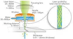
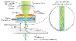
Laser technologies are best suited for machining such ultra-hard materials. Synova's Laser MicroJet (LMJ) process is capable of precision laser machining without any heat damage from a high-power laser beam (SIDEBAR). In the LMJ system, a laser beam, passing through a pressurized water chamber, is focused into a nozzle.
Laser technologies are enabling the design and manufacture of higher-performance gas turbine engines. As aerospace manufacturers strive to improve engine efficiency and reduce fuel consumption, they are redesigning turbine components and developing new materials to withstand ever-higher temperatures. When compared to using traditional dry lasers in machining such materials, Synova's Laser MicroJet (LMJ) technology features a water jet-guided laser to reduce heat-affected zones.
The low-pressure water jet emitted from the nozzle guides the laser beam by means of total internal reflection at the water/air interface. The water-jet diameter is usually between 30 and 80μm, and the laser power required is between 10 and 200W. While the principle looks simple, years of experimentation and optimization were required to fine-tune the process.
The technology behind LMJ is based on creating a laser beam that is completely reflected at the air-water interface, using the difference in the refractive indices of air and water (FIGURE 1). The laser is, therefore, entirely contained within the water jet as a cylindrical beam, similar in principle to an optical fiber.
The LMJ process works in two stages. The energy of the laser pulses vaporizes the workpiece material by heating while the water cools and cleans the surface in the interval between the pulses. Through a scanning process, a trench is formed that becomes deeper with each pass.
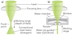
In contrast to traditional dry lasers, the LMJ wet laser technology cuts with a parallel beam, with a working distance that can extend up to several centimeters (FIGURE 2).
This is not the case with conventional lasers, where the focused laser beam has a limited working range of just a few millimeters from beam divergence. The beam converges at a focal point and then diverges, so a focus distance control is required and the working distance is short.
The LMJ process offers several advantages. There is no need for focal adjustment, which enables parallel kerf sides. There is minimum HAZ, thanks to the cooling effect of the water. Finally, there is a high removal rate with debris washed from the kerf.
Water-jet benefits
The water jet eliminates the complexity and process variations of maintaining the laser in focus typically associated with dry laser systems. Using water to guide the laser to the workpiece yields the following:
Water guides the laser. The application becomes insensitive to the focal plane of the laser. A cylindrical laser beam is created, resulting in perfectly parallel walls and tight kerf widths. It also enables the user to cut thick or non-flat parts without having to worry about being in focus.
Water cools the material. Heat is generated during laser ablation. When using a conventional dry laser system, the surrounding material absorbs a lot of laser energy, creating an unwanted HAZ. With LMJ, much of the heat dissipates into the water, so there is little HAZ on the workpiece. Stress-induced conditions such as micro-cracking, oxidation, thermal damage, or deformation are greatly reduced.
Water cleans the surface. When using a conventional dry laser, a portion of a laser-ablated material tends to redeposit and solidify, creating unwanted slag. With LMJ, the water displaces that material before it solidifies, translating into much cleaner entrance, wall, and exit surfaces without particle deposition or burrs.
Diffuser hole geometries
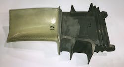
Film cooling in all of its various formats has become a mainstay of turbine cooling technology. The primary focus of most research has been on the use of discrete holes, or rows of holes, on the hot gas path surfaces of the turbine, as seen in the vane and blades (FIGURE 3).
Film cooling is performed almost exclusively through the use of discrete holes and rows of evenly spaced holes. All film-cooling holes are either round or shaped. Shaped holes are composed of round metering or throat sections with a uniform and symmetric expanded exit region on the hot gas surface. Most commonly, all shaped holes applied in practice have fan diffuser exits with divergence angles between 10° and 15° on each lateral side, as well as on the side into the surface.
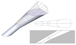
One major advance has been the change from round holes to fan-shaped or diffuser holes. Although the use of round cooling holes is prevalent, aerospace designers increasingly use more complex geometries such as diffuser holes. To enhance air flow, diffuser holes vary in shapes and depths to blend into the 3D shape of the part detail (FIGURE 4). Their geometries can range from tapered round cones to squares or rectangles. The final through-hole is often not centered to the outer diffuser shape.
These differing holes may have a specific form and function, either of limited or widespread potential, but each must also ultimately face the challenges of manufacturing, operability, and cost-effectiveness.
In the past, manufacturing constraints have limited the geometry of film holes. These factors included film hole length-to-diameter ratio, film hole axis angle to the external surface tangent, and the specification of the hole exit shaping. Laser machining with five-axis computer numerical control (CNC) has enabled these limitations to be overcome.
To address concerns about overall efficiency and metallurgical quality, hole drilling processes require maximization of machining speed, while improving control of the machining depth and location accuracy of each detail.
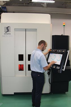
The five-axis MCS 500 system (FIGURE 5) integrates LMJ technology with a Makino-based platform. It is specifically designed for 3D machining and drilling of cooling holes in industrial gas turbine components. Super-alloy turbine blades with thermal barrier coating can be processed in one step, without cracks in the ceramic coating and extremely low recast in the metal structure.
As recently reported by GE Power, the technology team at the Advanced Manufacturing Works (AMW) facility (Greenville, SC) uses this system to drill cooling holes and diffusers that improve the overall performance of gas turbines. The AMW GE manager is also projecting labor savings of up to seven hours per part.
New wonder material
GE Aviation and GE Power have pioneered in developing ceramic-matrix composites (CMCs) to replace certain metal components in hot sections of jet engines and gas turbines. Components made of ceramic-matrix composites are one-third the weight of those made with metal alloys. They also allow gas turbines and jet engines to run hotter because their chemical properties allow them to reach higher temperatures without failing. Engines with these parts could run more efficiently and help reduce the overall weight of airplanes, which helps them to lower fuel burn and emissions while increasing their efficiency in the future.
Indeed, GE's CMCs can operate at temperatures exceeding the capability of current nickel alloys typically used in high-pressure turbines. Metal parts require extensive dedicated cooling air, which directly takes away from the primary engine airflow and reduces efficiency. CMCs, which are one-third the weight of nickel, can operate with little or no cooling, providing a significant efficiency boost to the cycle.
"GE has been very persistent in investing internal resources to push the CMC technology," said Jenn-Ming Yang, a materials science professor at the University of California at Los Angeles (UCLA). "Initially, they were trying to use CMCs in gas turbine engines for electricity production, and I think they have built up enough competence and experience to push it into engines for aircraft."
GE Aviation is the first company to introduce heat-resistant, lightweight CMC components into the hot section of commercial jet engines. It has set up a supply chain to mass-produce CMC components from a raw materials plant in Huntsville, AL, to full-scale production in Asheville, NC. The production facility in Asheville is already using LMJ laser technology to machine 3D CMC components to final dimensions. Meanwhile, the GE Power technology team in Greenville has also found that the MCS 500 system is especially suited for machining CMC components.
GE Power has gone a step further. It has developed patents based on LMJ technology to achieve higher productivity in laser machining of turbine parts. This partnership between supplier and user can only result in an expanded use of this laser technology to machine components for gas turbines and jet engines.
ACKNOWLEDGEMENT
Laser MicroJet is a registered trademark of Synova.
NITIN SHANKAR(nitin@vtx.ch) is a business development consultant for Synova, Duillier, Switzerland (www.synova.ch), and has been a contributor to ILS.
