Mohammed Naeemm
Thermal management key to processing
Aircraft manufacturers have been using fiber-reinforced plastic (FRP) composites for approximately 50 years, with usage increasing steadily each year as the industry discovers the advantages they can provide. Although initially more expensive than traditional materials, the efficiency, maintenance and fuel savings gained are so significant that they could potentially outweigh the initial cost of the aircraft.
Carbon and glass fiber-reinforced plastics (CFRP, GFRP) consist of a matrix of carbon or glass fibers bound in a polymer resin that offers a number of desirable properties – most notably a high strength-to-weight ratio, but also high rigidity, low thermal expansion, and good corrosion resistance.
Flying an aircraft manufactured using the lighter FRP composites is likely to translate to fuel cost savings of millions of dollars per year. For example, aircraft maintenance savings are believed to be in the region of $30 to 40 million over the lifetime of a Boeing 787 Dreamliner.
Despite the benefits of FRP composites, these materials are notoriously difficult to machine. Traditional processing methods, such as mechanical milling and drilling, can result in chipping, heat damage, delamination, fiber pull-out, and severe wear to the tool. Recently, water jet cutting has been investigated but still causes some fiber delamination among other practical limitations. For instance, it is necessary for a pilot hole to be drilled when the process starts anywhere other than the edge of the material.
As a non-contact material removal process, laser machining provides a solution to some of the issues highlighted. However, until recently, the laser-material interactions for this application were not widely understood. JK Lasers has conducted a study alongside Liverpool John Moores University to find out more.
To enable the researchers to better understand the interaction between the laser and the material, machining was carried out using two laser sources with different beam characteristics. Percussion drilling was carried out using a fiber delivered, high peak power Nd:YAG laser (JK300D) with a drilling nozzle. Cutting trials were carried out with a 200 W, single mode fiber laser (JK200FL) with a cutting nozzle. Trepanning and milling trials used the same laser but with a scanning head.
Laser-material interaction
The main factor affecting the machining of FRP is the very different properties of the carbon or glass fibers, compared to the polymer matrix. The laser power that is required to vaporize the fiber is much higher than that needed for the polymer.
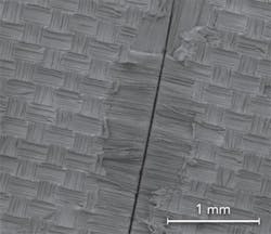
| FIGURE 1. SEM of fiber laser cut surface, showing slight surface thermal damage. |
The differing reactions of the components are most noticeable when processing CFRP. While the polymer only requires a small amount of thermal energy to vaporize, carbon fibers are very good conductors of heat, meaning that much of the energy is conducted away before it can cut the fibers. For this reason it is very important for high quality laser processing that the heat input to the material is carefully managed
Two different assist gases were used during the percussion drilling trials with the Nd:YAG laser: nitrogen and carbon dioxide. The results suggest that the type of assist gas used can have an overall effect upon the quality of the holes.
When using the N2 assist gas, a fine layer of thermally decomposed polymer matrix was left on the surface of the sample. However, the FRP that had been processed with the CO2 assist gas showed an improved surface quality. This result is due to the superior cooling quality of the CO2.
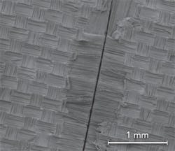
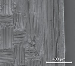
When cutting the FRP composite with the fiber laser, less thermal damage was caused. This is due to the laser's small spot size. FIGURES 1 and 2 show SEM images of the fiber laser cut surface and the thermal damage that occurred. It is clear that the damage was limited to a single layer of the composite material.
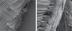
| FIGURE 3. Edge cut quality comparison between mechanical cut (left, 500x) and fiber laser cut (right, 1200x). |
These results are extremely positive for the aerospace industry. As the bulk of the material was not affected by the laser processing, the composite will remain strong and stable.
FIGURE 3 shows a comparison between the edge quality produced with mechanical shearing and cutting with the fiber laser. While the mechanically sheared sample shows fibers protruding from the bulk of the composite, the laser-cut sample shows a clean edge.
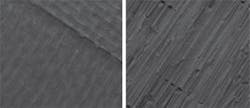
| FIGURE 4. Laser micromachined composite surfaces, 200 mm/sec, air assist gas (left, 80x; right, 500x). |
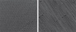
Similar to the results gained during the cutting trials, the laser milling tests show that the fiber laser's small spot size is beneficial for this application. The fibers exposed by the laser show no sign of thermal damage, while the matrix material shows only slight evidence of melting when viewed with an SEM at high magnification (FIGURES 4 and 5). The outcome of this trial is promising as it opens up the possibility of using fiber lasers for the milling of aerospace composite materials.
The same fiber laser (JK200FL) was also used to trepan 2 mm diameter holes in FRP composite materials. Cutting trials revealed that for composites over a thickness of 1 mm, trying to process the material as though it were a metal did not produce a satisfactory cut.
A larger kerf that would allow the material to escape without the matrix adhering to the freshly cut face was required. The strategy devised was laser spiral drilling.
The edge quality on the surface of the laser spiral drilled holes appeared to have suffered from less thermal damage compared to the holes that had been percussion drilled with the Nd:YAG laser. The amount of burn back on the top surface was only a few tens of microns.
| FIGURE 5. Laser micromachined composite surfaces, 250 mm/sec, CO2 assist gas (left, 50x; right, 500x). |
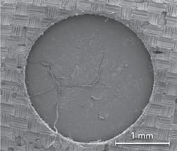
The results of the drilling trials with the fiber laser show that the speed of laser processing with a scanning head, combined with the open architecture of the hole geometry, reduces the damage to the matrix material on the surface of the FRP composite. FIGURE 6 shows an image of the GFRP composite that has been laser spiral drilled.
Summary
The results of the trials conducted – using the fiber delivered, high peak power Nd:YAG laser and the 200 W, single-mode fiber laser – show that lasers are able to provide the quality of processing in a way that traditional techniques are unable to do. Thermal management is the key to processing FRP composite materials. As demonstrated during the YAGH laser trials, the use of an assist gas such as CO2 can considerably reduce the damage caused by the laser beam.
The trials with the fiber laser suggested that the small spot size and the resulting carefully targeted heat input was beneficial when processing FRP composites. Fiber lasers with a high beam quality, small spot size, and the option of using a scanning system were proven to be well suited to machining these materials. The results also suggest that strategies such as laser spiral drilling will play an important role in future laser processing applications for the aerospace and automotive sectors. ✺
Dr. Mohammed Naeemm([email protected]) is global key account manager at JK Lasers, part of the GSI Group.
