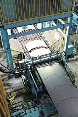
Laser system minimizes waste and reduces costs
KENICHI FUKAMI
Remarkable progress has been seen in lightweighting of automotive parts because of expanded use of high-tensile-strength steel and aluminum. However, most of the cost for lightweighted parts is the raw material—especially for press-blanked parts, where a large amount of material is wasted because of scrap produced during the cutting-out process from sheets or coil. Also, for press blanking, a die is required for each part—therefore, die manufacturing, die change, and die storage are inevitable.
Minimizing waste and die-related cost not only leads to part-cost reduction, but also reduced energy and CO2 produced during material production—a challenge for the automotive industry, which uses a large amount of materials. Honda's solution was to develop a die-less Intelligent Laser Blanking System (ILBS) for mass production.
Aim of ILBS
Press blanking with a die is a process that has been widely used for mass production in the automotive industry. Contrary to its high productivity, the drawback of using a die is its expensive manufacturing cost and the need for long-term storage space. Also, material yield rate of the blanked part is not optimal because of the restrictions of tool edge design caused by minimum curvature.
By applying laser blanking to automotive sheet metal production, no die is required and press hardening could be avoided, leading to higher design freedom, lower cost, and higher formability, which are the advantages to conventional press blanking. However, laser blanking is mostly used in low-volume prototyping because of its overwhelmingly slow process speed compared to press blanking.
Increasing laser blanking process speed is essential to maximize its advantage over press blanking. Honda utilizes ILBS for mass production by developing three key technologies: high-speed laser cutting, a high-acceleration H-gantry system, and a continuous-feed conveying system (FIGURE 1).
High-speed laser cutting
Laser cutting involves melting of the sheet metal by applying heat and removing molten metal by applying gas. Therefore, it is important to increase heat energy density and to optimize assist-gas condition to increase the cutting speed. We have used a 5kW fiber laser with a spot diameter of 50μm to improve heat energy density. For the assist gas, we have used nitrogen instead of compressed air to avoid oxidization on the cut surface for better quality.
First, we demonstrated that a cutting speed of 120m/min (sheet thickness: 0.6mm) was possible using a high-power laser with optimized assist gas condition and standoff (nozzle tip to work distance). Standoff is an important parameter for laser cutting, as this will have a direct impact on laser focus point and assist-gas flow rate. When we say "possible to cut," this means that the standoff has enough tolerance to resist disturbance during mass production.
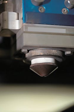
In actual cutting, standoff changes because of laser head vibration and sheet metal waviness result in defocus of the laser spot, producing a cut problem. We used a lightweight laser head that weighs one-third less compared to a conventional laser head with same optical performance, allowing us to reduce inertial force on the gantry to avoid machine vibration during acceleration (FIGURE 2).
Sheet metal waviness is an important factor for the standoff. Like a conventional system, the capacitive displacement sensor on the laser head tip constantly measures the distance between the sheet metal, which is then fed back to the z-axis motor of the laser head to stabilize its standoff. We improved the measurement frequency and the processing speed to correspond to the cutting speed of ILBS, which is much faster than a conventional system.
By improving heat energy density, stabilizing standoff, and optimizing assist-gas condition, we have realized a cutting speed 3X faster than a conventional laser cutting system in a mass-production environment with disturbances such as machine vibration.
High-acceleration H-gantry system
The laser head needs to move freely in the 2D plane to cut square-, bow-, and complex-shaped blanks. As the trajectory of the laser head establishes the dimensional accuracy, the repeatability of the position, as well as the accuracy of the movement, become important.
When cutting a complex shape, the process time increases significantly because the laser head needs to move along various curves, which involves acceleration. Therefore, the laser head needs a high-acceleration, high-precision drive system.
Generally, with industrial robots, acceleration is not high enough and the repeatability of the position is guaranteed, but not its trajectory. When using a linear-motor-drive system to improve precision and acceleration of each axis, enormous drive force is required, resulting in high power consumption and overheating of motors during continuous operation. From the law of motion, a = F/M (where a = acceleration, F = force, and M = mass), reducing weight is the best way to improve acceleration.
An H-gantry consists of four fixed servo motors and driving belts. By controlling the rotation of the servo motors on the left and right, the belt moves the laser head in the x- and y-axis directions as required. It is a unique driving system without an actuator on the driven part, resulting in a lightweight design.
Furthermore, by using lightweight, highly rigid carbon fiber-reinforced plastic (CFRP) to reduce weight and deformation of the frame, we have achieved an acceleration of 10G when compared to 3G with a conventional steel frame. Also, by using a urethane belt with a carbon-fiber core, we have reduced 50% of the precision problem because of elongation.
By optimizing the key elements affecting the rigidity of the H-gantry, we have realized high acceleration and improved trajectory precision.
Continuous-feed conveying system
In conventional press blanking, the material is fed into the press and at a certain length, the feed stops and the sheet gets blanked, which is repeated until the full coil has been pressed and exhausted. This means that during the feed, the die does not work. With the ILBS, we have eliminated this downtime by realizing a continuous-feed conveying system to improve productivity of the line.
To establish a continuous laser cutting process, securing space underneath the laser head and stabilizing the feed were issues. In general, laser cutting a sawtooth support underneath keeps the sheet flat during cutting. The problems with the sawtooth support is that the sawtooth itself is cut at the same time, so cutting failure occurs because of the blocking of molten metal discharge during high-speed cutting.
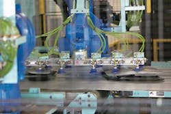
For that reason, we developed a conveyor that could secure space underneath the laser head. A spatter box is placed under the laser head, which is synchronized with the laser head's y-axis movement so that it can collect spatter safely the whole time. This unique conveyor system uses CFRP to reduce weight and increase rigidity to synchronize with the high-acceleration H-gantry system.
Because of this synchronized system, we can cut large parts such as the side panel outer (SPO) with a length of more than 3m and small parts such as the rear inner panel-both inside a process area of 2 × 2m.
Spatter collector and automatic cleaning system
The ILBS cuts 10–20 tons of coils in a day, leading to concern about collecting dozens of kilograms of spatter per day. In conventional laser cutting, a fume collector is used to collect minute spatters only. The ILBS uses a spatter box to collect and prevent spatter from scattering, which is connected to a fume collector designed to collect spatters of different sizes.
We have increased collection efficiency and maintained suction force by reducing clogging of the filters, which normally needs regular maintenance. We have also minimized the influence on productivity by using an automatic cleaning system, which cleans the filter during the coil change.
Implementation result of ILBS
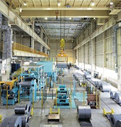
Since October 2015, we have been blanking many parts such as the SPO and roof using the ILBS, which is the first dieless blanking line in the automotive industry (FIGURE 3). Dies for the current model exist because production had already started before implementation of the ILBS, but models from now on do not use dies, so there is no requirement for storage space or a turnover machine. Dies of the previous model had to be stored for 10 years after the end of production for spare parts—but with the ILBS, only the required data can be saved almost permanently.
Typically, a blank is designed with a margin to tolerate the misalignment that could happen during the blank setting in the press forming process. If this margin is not required, the yield rate could be improved by rewriting the program to reduce the margin during production. Also, press forming problems such as cracks can be solved by optimizing blank design immediately just by rewriting the program. Other advantages, such as improvement of press formability and reduction of press load, lead to the replacement of press blanking of high-tensile-strength steel to ILBS.
Summary
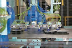
By developing the ILBS, we have revolutionized the manufacturing process in the automotive industry (FIGURE 4). We would like to keep improving the ILBS in cooperation with our user to eliminate dies from the blanking line around the world. In the future, we would simultaneously send the cutting program from Japan to each plant for the new models and establish a system to solve press problems immediately.
KENICHI FUKAMI ([email protected]) is a staff engineer at Honda Engineering Co., Ltd R&D Division, Tochigi, Japan; www.honda.co.jp/eg.
