Reduced power and cost per part are benefits
JASON HILLENBRAND
By now, most manufacturers know about the benefits of fiber laser cutting over the long-time standard of carbon dioxide (CO2) laser processing. Faster cutting speeds and lower maintenance costs have driven sales of fiber lasers to surpass those of CO2 lasers in only a few years. The decision to make the jump from CO2 to fiber has been justified by almost everyone who has done it. One example is where a 4kW fiber laser has taken the place of three 4kW CO2 lasers, with capacity to spare—allowing production of more parts in a third of the floor space while dramatically reducing maintenance and electrical costs.
Almost as popular is automation. Just like any single laser in the past, the consequence of one machine producing 3X the number of parts is how to handle the material, parts, and scrap. There are articles and seminars dealing with this issue, as well as other downstream processes such as bending and welding. These are the up-front, "in your face" problems that must be dealt with. However, technology continues to be developed in the laser itself to handle the unseen loss of green light on time and overall productivity.
It was only seven or eight years ago when fiber lasers were sold primarily as a lowest-cost-of-operation machine. It didn't take long before cutting speeds became the primary topic of fiber sales vs. CO2. Manufacturers are constantly looking at these benefits to increase productivity while reducing cost per part.
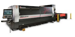
In doing so, however, there have been some compromises along the way, primarily in edge quality and cut capacity. This has led some manufacturers to hold on to their older CO2 machines, or even those who simply do not think fiber is right for them at all. However, current fiber laser technology (FIGURE 1) is now eliminating any remaining excuses against buying a fiber machine.
FIGURE 1. The Amada ENSIS fiber laser.
Fiber laser benefits, challenges
Material handling automation is almost a necessity when it comes to fiber lasers. All too often, companies invest in the highest-powered machines, only to see a green light on time drop because the machine is waiting to unload or reload due to its speed. Load/unload systems have an immediate impact on the productivity of the laser and the cost of the part itself. By automating many of the features within the machine, customers can even further reduce the cost of making a part. As small as that seems, it adds up quickly and helps manufacturers maintain a competitive edge in today's market.
The most recent of these features is the ability to manipulate the laser beam itself, resulting in edge quality that rivals any CO2 machine. This is especially important for those companies processing thick plate with oxygen as an assist gas.
Fiber lasers are the dominant choice when cutting with nitrogen as an assist gas. Fiber cutting speeds are 3-4X faster when compared to their same-wattage CO2 counterpart. But when processing thicker plate, this application requires oxygen (O2) instead of nitrogen (N2) for assist gas. This means that the machine can no longer use full power, so any speed advantage for fiber is eliminated.
The thickness where one would change from N2 to O2 will vary based on laser power and manufacturer. The hurdle for fiber lasers to overcome has been the cut edge quality when processing plate material with O2 compared to CO2. Generally, the results showed heavier striations and an overall rougher appearance, mostly due to the mode—or shape—of the laser beam generated by fiber laser engines.
The same features that allow fiber lasers to be a dominant force in thin material processing are their undoing when cutting thick plate. Fiber lasers produce the perfect bell-shaped Gaussian curve to generate a TEM00 mode. This style of laser beam produces a very fine, high energy-density beam for maximum power in the smallest area to vaporize material quickly for the fastest cutting head movement.
As the material thickness increases, a point is reached where the high-pressure N2 being used to force the remaining molten material through the bottom of the kerf can no longer do so without leaving a burr or dross along the bottom edge. Now, the application requires an assist gas change from N2 to O2—the power must then be reduced as O2 propagates the burning process.
The narrow, high-density beam of a fiber laser creates difficulties when expelling the molten metal during the cutting process. The effect of speed combined with excess heat generated by a fiber beam leaves a less-desirable edge in thick plate. By comparison, a CO2 laser produces more of a flat-top mode, where the concentration of power is distributed in a ring pattern or "donut shape." This is what helps CO2 lasers produce better quality edges in thicker material.
Improved edge quality solutions
There have been solutions over the years to mitigate the edge quality difference that has allowed some manufacturers to still laser-cut their plate on their new fiber laser machines. These solutions generally were manual processes and did not necessarily directly address the real issue of the mode of the fiber laser-instead, it masked it.
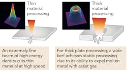
The most common was to use additional optics in the cutting head to widen the spot density. By doing this, the cut width or kerf is wider, allowing for more O2 to assist in the cutting process and more molten material to be evacuated out the bottom side of the cut (FIGURE 2). The heat at the point of incidence is dissipated somewhat, further improving the edge quality.
FIGURE 2. The narrow beam is ideal for high-speed processing of thin material, but the wider beam is best for thick material.
Another solution involves changing the cutting lens to a special lens that literally changes the beam mode from that of a fiber laser, to the same mode typically found on a CO2 machine (TEM01). The result in thick plate is exactly what one would expect from a CO2 machine, thus helping eliminate any objections for fiber technology.
Fiber lasers possess the ability to automatically change the beam mode based on the material being processed, without the need for an operator to manually change or adjust anything in the machine. Complementing an automatic material handling system, or an auto-nozzle changer, fiber lasers can now set the laser beam quality to CO2 mode for thick plate processing, without the need to compromise quality if there is no operator available to complete a setup between jobs.
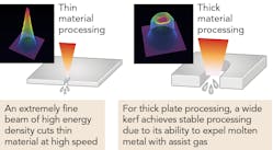
Some systems change the beam mode directly from the fiber to the typical CO2 donut-shape mode, while other systems can infinitely change the mode based on the specific thickness of the material to be processed (FIGURE 3). Either way, manufacturers can now produce quality parts through the entire range of thickness in a totally automated environment.
FIGURE 3. Infinite mode change allows for ideal beam quality for all material thicknesses.
Business impact
The power of this technology is obvious, but there are still conclusions to be learned. For example, the idea of a 2kW CO2laser being expected to cut 1in. mild steel plate on a regular basis was simply unheard of in the industry. There were tricks or modifications that could be done to make this happen, but no laser manufacturer specified that their 2kW CO2 laser would do this constantly.
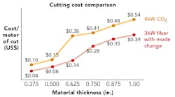
However, with the ability to manipulate beam mode, the industry has found that a 2kW fiber laser, when using the proper mode setting, can cut thick plate up to 1in. or even higher on a regular basis. And it does this with speeds similar to a 4kW CO2 laser, producing the same edge quality. Furthermore, a 4kW CO2 laser will consume around 50-60kW of power, whereas a 2 or 3kW fiber laser, producing the same quality part in the same amount of time, consumes only 10-15kW of power and there are no optics, gases, tubes, etc. to maintain, so the cost of that part has been dramatically reduced. Some studies have shown a cost-per-part reduction of more than 50% (FIGURE 4).
FIGURE 4. Fiber laser technology yields more parts per hour at a lower cost per part.
Now the industry asks, "How much power do you really need?" As powers increase, we continue to learn more about the capabilities of what we already have. Is the additional capital investment for higher power necessary? Is the additional cost of electrical consumption for higher powers worth it? The answer will depend on your application, and many times will be "yes, it is worth it." However, when we look back, we begin to see a common theme developing—doing more with less seems to be a constant when it comes to fiber vs. CO2laser technology.
JASON HILLENBRAND ([email protected]) is the General Manager - Blanking Products for Amada America, Buena Park, CA; www.amada.com/america.


