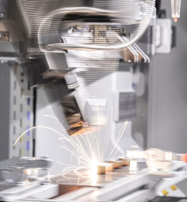
Machine with one head for cutting and two heads for welding is shown.")
In order to meet tightening environmental regulations, the exhaust systems of today’s cars and trucks have become quite complex. The exhaust system in a commercial vehicle can now be the second most expensive module after the engine. Passenger car exhausts can include diverter flaps to alter the gas path for different load conditions, Exhaust Gas Recovery (EGR) systems that reduce nitric oxide (NOx) emissions and get the engine up to temperature more quickly, and urea injection systems to tame diesel emissions. All of these new active exhaust control components require more sensors in the system and additional threaded fittings to mount the sensors.
Traditionally, a threaded sensor boss machined with a complex saddle shape would be welded onto the intermediate pipes using metal inert gas (MIG) welding with filler wire, either manually or in a robotic cell. For mounting bosses to sheet metal components, projection welding would be used, requiring another type of boss with a tapered projection. As the need for sensor bosses increased, a tier 1 exhaust manufacturer started looking for a faster and less costly assembly and welding method. Sequential laser processing, a new cutting-edge method of installing components in sheet metal or tubular parts with a laser, has arrived (FIGURE 1).

The idea of sequential laser processing is to load the workpiece into a tooling fixture one time, and then laser-cut precision features into it (FIGURE 2) and laser-weld other components in place (FIGURE 3) to build up an assembly without ever removing the part from the fixture. By laser cutting the hole for a sensor boss just before welding, the hole is precise enough for autogenous laser welding, and the hole’s exact position is known at all times by the work cell controller. The high level of precision lends itself to automated part placement and automated welding, giving exhaust manufacturers a fast, reliable process that offers a host of advantages (also see TABLE):
- Faster cycle times
- Simplified boss design because they no longer require saddles for tube mounting or projections for sheet metal.
- Filler wire is eliminated because the precise laser-cut holes match the diameter of the boss, allowing autogenous laser welding.
- Heat distortion is reduced in sheet metal components, thanks to the laser weld.
- The weld is also cosmetically more appealing.
- Shorter weld tool path (thanks to a new zero offset rotary weld head)

New process finds more uses at the customer
The new laser processing solution turned out to be a home run for reducing the material costs and cycle times for their sensor boss welding. The customer’s first new machine got them thinking of other exhaust components where they had recently applied laser technology. They immediately realized that exhaust flaps and urea mixers, where they had already employed laser welding systems, could also benefit from the cut, position, tack, and weld sequential process.
EGR diverter flaps are used to bypass EGR cooling modules during the engine warm-up phase so that the engine reaches peak efficiency more quickly. When the engine is at normal operating temperature, the flap will then feed exhaust gases through the EGR assembly to reduce NOx emissions. Because they are located near the engine in the hot end of the exhaust, the EGR components need to be robust. Hydroformed housings are commonly used at the input of the EGR module to connect the exhaust pipe and house the diverter flap. In order to seal off exhaust flow when not in use, the flap housing must be a precise component.
The idea of using a sequential laser processing machine to produce the flap housing allows them to fabricate two inexpensive stamped half-shells into a precision housing (FIGURE 4). First, the two stamped half-shells are loaded into a tooling fixture, where they are laser-trimmed to precise dimensions by two laser cutting heads—effectively changing typical stampings into precision components. Then, the same tooling fixture pushes the two half-shells together and the laser welding head moves in and seam-welds the half-shells into one piece, again in one smooth operation with no operator intervention.

Machine evolves into a widely usable tool
Since they were already laser welding exhaust flaps in some facilities, the customer asked if flaps could also be laser-welded on the same system by swapping out one tooling fixture for another. In this case, the cutting feature is not required, but the ability to place the flap inside the shroud and then weld it to the shaft makes it a good application for the same laser machine. This desire to run multiple applications across one machine led to the idea of using tooling pallets with quick disconnects for power, pneumatics, and control signals. Finally, a dual cabin system was utilized in the new machine so that multiple jobs could be run at the same time (FIGURE 6). The customer would load the two quick-change tooling pallets for whichever jobs they need to run and utilize a production mode that processes one part while the other cabin is being re-loaded.
Having developed a new laser process and then a multipurpose laser machine tool, the same customer had found a number of uses for the for the FLC system and ordered their second machine. Urea mixers, used to mix the injected urea into the exhaust gases of a diesel engine, could have their inner components laser-cut, be robotically assembled, and then laser-welded together to build a three-dimensional assembly—all without human intervention.
Precision cutting prior to welding
Experienced automated welding experts often admit that “not all parts are ideal candidates for automated welding” because any automated welding operation requires a high level of repeatability in weld joint location. This is doubly true if the weld source is a laser producing precise, narrow weld joints. When trying to laser-weld formed sheet metal components, you’re combining parts that have dimensional variations with a welding source that is not tolerant of changes in joint location.
Sequential laser cutting is an elegant solution because it is able to essentially cut the precision into a formed component just prior to welding. This guarantees that the weld joint will be in a known and repeatable location every time. Because the different applications were foreseen early by the customer prior to the first machine build, Weil Technology (Müllheim, Germany) was able to maximize utility of the machine with quick-change tooling pallets.
According to Andreas Scholz at Weil, “It was an unusually holistic laser application and machine development program that grew out of multiple projects for the exhaust industry.” An application developed for one specific customer now looks widely applicable to other industries. “We are now finding applications for sequential laser processing in other fields such as appliances and hardware fixtures. And because the machine was originally developed for multiple assemblies and fast job changeover, we are able to apply the technology to new fields in an unusually rapid fashion.”