Improvements in process cost and speed are needed to achieve good part quality
SEAN BERGMAN
Laser additive manufacturing (LAM) is rapidly becoming an important method for the fabrication of both prototype and production metal parts. However, the technology is really just in its infancy, and significant work still needs to be done in the development of new materials and in understanding how various process parameters affect results. In particular, LAM methods typically have a relatively small process window for laser performance, where minor changes in beam and scanning parameters can significantly affect results quality. This article examines the need for laser beam characterization to deliver optimum results, and then shows how a new beam monitoring technology enables rapid measurements in laser-based 3D manufacturing systems. Ultimately, this technology will allow beam issues to be identified and corrected before they seriously impact the quality of parts produced using LAM.
LAM basics
Most traditional machining techniques are subtractive. That is, they selectively remove material from a substrate to create the desired shape. Additive manufacturing methods work the opposite way, building up a part layer by layer from nothing. Powder bed fusion (PBF), the primary LAM technique for producing finished parts (see "LAM techniques"), is essentially a form of 3D printing that uses metallic powders and a laser source to melt them.
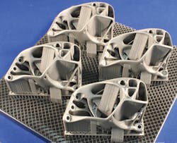
In PBF, a layer of metal powder about 20–60μm thick is first spread evenly with a recoater blade over a build plate, which is a platform that can be moved vertically. Then, the laser is scanned over the powder to selectively melt and resolidify it in the desired pattern for that layer. After a layer is finished, the powder bed is lowered an amount equivalent to the thickness of the layer, and a new layer of powder is spread over it. The laser writes that layer, and the process is iterated until completion. At the very end, the remaining unmelted powder is removed to reveal the finished part (FIGURE 1).
PBF usually employs near-infrared (NIR) ytterbium fiber lasers in the 200–500W power range. These are scanned in two dimensions (x and y) and focused with a high-quality f-theta scan lens to achieve a spot size in the 100μm range. This combination of power and spot size easily produces sufficient fluence to rapidly melt metal powders. In fact, it's important that the power density is not so high as to cut or drill the build plate, or to penetrate too far into the metal powder. Optimally, the laser should completely melt through the new layer of powder and a small amount of the previous layer to completely fuse the two and produce uniform material properties throughout the entire part.
Current LAM applications
The flexibility and speed of 3D printing with polymer materials have made it a widely used tool for engineering and prototyping purposes. The ability to work with metals and deliver finished parts that have robust mechanical properties extends PBF into a useful technique for the fabrication of actual production parts in a variety of industries, including aerospace, dentistry, motor racing, and even jewelry.
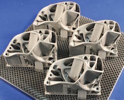
Specifically, PBF is most effectively employed for producing high-value, critical parts that are both mechanically intricate and costly to produce using other methods. Examples would be shapes having complex curves, and internal holes and channels (FIGURE 2).
A standout example of PBF is the production of the fuel nozzle for the Leap jet engine at GE Aviation [1]. According to GE Aviation, this single part—created with internal support structures and cooling pathways—replaces a machined assembly consisting of 18 separate pieces. The LAM-produced part is 25% lighter and about five times more durable than the machined equivalent. Since each Leap engine incorporates 19 of these nozzles, this weight reduction results in a noticeable fuel savings.
Technology challenges
While there are already a number of sophisticated, turnkey PBF systems commercially available, these don't provide the intimate level of process control necessary for success in some applications. For example, there are various considerations related to part orientation during fabrication that can cause difficulties with the deposition process, or lead to undesirable stress characteristics in the finished product. These can't always be completely addressed with current commercial systems.
There are also material-related cost challenges with commercial LAM systems. For instance, while these systems work with a variety of powders, including aluminum, cobalt, titanium, stainless steel, and nickel alloys, each one requires a different set of deposition parameters. In many instances, these are proprietary to the machine supplier and must typically be purchased individually at a price in the $10,000–20,000 range. And, since they are directly downloaded into the machine, the user still may not have access to all the parameters necessary to optimize or modify the process for their particular needs.
In terms of materials, it is also important to note that the powders currently in use are essentially all alloys that were developed for traditional, wrought metal manufacturing techniques (which usually involves multiple steps of melting, forming, and subsequent thermal processing). They also don't yield the same desirable bulk physical properties (such as tensile strength) when just rapidly melted and resolidified during LAM. So, an important area of research is the development of new materials that will deliver improved physical characteristics specifically when utilized in LAM. In fact, this is critical to expanding the utility of the technology.
As a result of these factors, there are numerous research groups and end users who wish to modify existing systems or build their own LAM systems that will enable them to completely investigate and control every process parameter. This enables improved results and the development of a more clearly deterministic process.
Beam metrology needs
While there are well over 100 process parameters specified in the software of most LAM systems, some of the most critical ones—which the operator has little control over—have to do with the power, shape, and size of the focused laser beam since these ultimately determine the dimensions of created features and the physical characteristics of the material. This makes beam metrology particularly critical to the process.
Beam variations occur because of several factors. First, there may be some inherent power drift in the laser output. Next, the output power levels used in PBF are sufficient to cause thermal lensing in the beam delivery optics, which can change the beam waist position as well as distort the spot shape. Also, since the beam is scanned over a wide field of view, the spot shape will usually be elongated at the edges of the field.
These considerations lead to a direct need to measure laser power, spot size, mode details, and beam waist location within PBF systems. In particular, it's necessary to acquire these measurements after the final f-theta scan lens rather than at some intermediate point in the optical system so that the beam has already encountered all possible factors that might affect it. Furthermore, it's ultimately desirable to develop a rapid measurement method so that power density and beam waist location could be measured between each layer write cycle without significantly slowing deposition down. This would enable any necessary corrections to be made on the fly to laser output. Alternately, it could automatically abort a build cycle, which can be in the 20–60hr. range for PBF systems with about 10 × 10in. build platforms if the process has gone significantly off track.
Novel beam metrology solutions
Unfortunately, there are limitations with the traditional techniques for measuring laser mode, waist location, and power that compromise their use in this application. Specifically, laser mode measuring instrumentation usually operates by sequentially scanning a slit or aperture across the laser beam at multiple distances from the source. This allows a full picture of the propagation characteristics (mode) to be acquired and the precise beam waist location to be identified. However, this type of instrumentation is relatively slow and bulky.
Similarly, direct power measurement of high-power lasers has traditionally been accomplished with thermopile detectors. While this technology can handle the high average laser power in LAM systems, it would be too slow (a measurement usually takes several seconds) to achieve in-process monitoring between each powder layer during part fabrication.
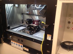
Now, a novel system from Haas Laser Technologies (www.haaslti.com) addresses both these issues. It can deliver very rapid measurements of beam mode and power for both continuous-wave (CW) and pulsed high-power lasers. Specifically, their Beam Waist Analyzer Camera (BWA-CAM) measures several laser parameters, including the beam waist position, beam size, and beam quality (M2) of high-power lasers in one fast (<1s) measurement. Plus, the system is sufficiently compact to enable easy use, or even integration, within the build area of LAM systems (FIGURE 3).
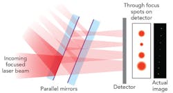
To accomplish this very comprehensive set of measurements, this device acquires several simultaneous, through-focus images of the laser spot using a clever optical arrangement (FIGURE 4). Incoming focused light is first attenuated and then directed into a pair of parallel plates, which are tilted with respect to the optical axis. The two interior surfaces of the flats are both coated with a high reflection coating so that only a small percentage of the light exits the system at each reflection. This transmitted light forms a series of spots on an array detector, which each show the beam profile at increasing distances along the optical axis. This optical arrangement can be adjusted so that the increment between adjacent spots on the detector represents spacings along the optical axis from 100μm to 12mm. System software analyzes this series of spot images to derive all the previously mentioned beam mode and waist location parameters.
Ultimately, the critical laser parameter in PBF is the power density at the precise point where the powder is being melted. Once the beam size is determined, laser power is directly measured (allowing power density to be calculated) within the BWA-CAM using a Coherent PowerMax-Pro detector. This utilizes a relatively new type of transverse thermoelectric detector technology, first introduced to the market in 2014, which combines the broad wavelength sensitivity, dynamic range, and laser damage resistance of a thermopile with the response speed of a semiconductor photodiode [2].
This unique set of characteristics is particularly beneficial in this application. Unlike a photodiode, which saturates at very low light levels, the detector measures high laser power directly in tens of microseconds. This minimizes the need for attenuating optics in the beam path, which can be a source of absolute measurement error. Also, in contrast to a photodiode, the response of this detector is highly linear, and the entire power measurement system (detector/electronics/software) is calibrated and NIST-traceable. Therefore, it delivers highly accurate, absolute readings of laser power. This is critical to know in order to optimize process parameters, or for analyzing the precise laser/material interaction in the development of new alloys.
The high response speed of the detector also enables it to directly observe pulse shape, rather than simply report average power. This is useful because deposition quality (e.g., grain size, tensile strength, etc.) is dependent upon peak power, rise time, and other pulse parameters. And, even when working with CW lasers, it's important to know how fast the laser reaches full power when powered on.
In conclusion, LAM represents a revolutionary step forward in metal fabrication technology. But for this technique to achieve its maximum impact, improvements are necessary in process cost, speed, and resultant part quality. High-speed, compact, and cost-effective beam diagnostic tools that deliver beam waist location, beam size, and power density information in <1s will be a key element in achieving these ends.
ACKNOWLEDGEMENTS
The author wishes to thank Dr. Rich Martukanitz, Director of the Center for Innovative Materials Processing through Direct Digital Deposition at the Pennsylvania State University, and Michael Scaggs and Gilbert Haas of Haas Laser Technologies, for their invaluable help in the preparation of this article.
BWA-CAM is a registered trademark of Haas Laser Technologies.
REFERENCES
[1] T. Rockstroh, D. Abbott, K. Hix, and J. Mook, "Additive manufacturing at GE Aviation," Industrial Laser Solutions, 28, 6, 4–6 (Nov/Dec. 2013).
[2] S. Bergman, "Laser power measurement: Time is money," Industrial Laser Solutions online (Aug. 2015); see http://bit.ly/1DYC1Z2.
SEAN BERGMAN([email protected]) is product manager for laser measurement instrumentation at Coherent (Santa Clara, CA); www.coherent.com.
LAM techniques
There are two basic categories of laser additive manufacturing techniques for producing metal parts: directed energy deposition (DED) and powder bed fusion (PBF). In DED, metallic powder is fed into a moving laser beam, and is melted and deposited onto the surface to create each layer. Typically, both the beam and powder feed mechanism are moved over the part in unison to create the desired shape.
DED commonly utilizes relatively high-power, near-infrared, fiber-delivered lasers in the 500W to 10kW range. These can be ytterbium fiber lasers, Nd:YAG lasers, or direct diodes. Spot diameters at the work surface range from 500μm to 5mm, depending upon power. DED is not a high-precision process—rather, some machining is usually required after deposition to obtain the finished part dimensions.
PBF, described in this article in detail, is a significantly more spatially precise process than DED. It delivers parts that are essentially at their finished dimensions, with accuracies at the micron level. However, maintaining this level of accuracy requires a high degree of process control. This article specifically describes beam metrology technology useful for accomplishing this, entirely in the context of PBF manufacturing.


